 |
MONOGRAPH  |
The Kangâmiut dykes in West Greenland: markers of the tectono-metamorphic evolution of the southern Nagssugtoqidian orogen and its foreland
Abstract
The general extent and structural evolution of the southern Nagssugtoqidian orogen of West Greenland were first described by Hans Ramberg who based much of his paper on the deformation of the regional Kangâmiut dyke swarm. The southern boundary is marked by a transition from undeformed, discordant dykes in the south to highly deformed dykes and host rocks to the north. Our analysis of the southern Nagssugtoqidian orogen and its southern foreland uses a comprehensive compilation of available data and covers the area from Sisimiut in the north to Alanngua, south of Maniitsoq. This represents almost the entire c. 200 km latitudinal extent of the Kangâmiut dyke swarm and encompasses the complete range of Nagssugtoqidian overprint on these dykes and their country rocks. South of Itillip Ilua (Itilleq), the structural and metamorphic overprints on the dykes exhibit a considerable range in both intensity and P–T conditions between and even within outcrops. In contrast, north of Itillip Ilua, the rocks show more systematic gradual increases in the degree of structural overprints and metamorphic grade, culminating in the Ikertooq thrust zone where granulite facies rocks are brought southwards over amphibolite facies rocks. Currently, available age data from the Nagssugtoqidian orogen permits the identification of two metamorphic episodes at c. 1850–1800 Ma and c. 1780–1720 Ma. These groups of metamorphic ages are supported by recent 40Ar–39Ar ages from dykes in the same area, which cluster at c. 1860 Ma and c. 1740 Ma, respectively. Albeit geographically sporadic, both age intervals support a subdivision of the Nagssugtoqidian structural and metamorphic overprints across the southern Nagssugtoqidian orogen and its foreland into two distinguishable temporal phases. Further geochronological investigations may well, however, find these two phases to be part of a tectonic continuum. For now, it is thought that the older event records south-directed thrusting over the foreland and concomitant loading of this crust, at least as far south as Maniitsoq. This c. 1860–1800 Ma crustal shortening and thrusting likely also closed a depositional basin located at the current latitude of Ikertooq, which could have formed during an early-orogenic extensional event that enabled and accompanied the c. 2035 Ma emplacement of Kangâmiut dykes. Up to 50–100 Ma later, a younger (c. 1780–1720 Ma) phase of shearing and thrusting mainly affected the Itillip Ilua – Ikertooq area and likely overprinted elements of the former event. This local younger overprint generated a separate trend of distinctly northward-increasing deformation and metamorphism.
Citation: Korstgård et al. 2024: GEUS Bulletin 58. 8312. https://doi.org/10.34194/geusb.v58.8312
Copyright: GEUS Bulletin (eISSN: 2597-2154) is an open access, peer-reviewed journal published by the Geological Survey of Denmark and Greenland (GEUS). This article is distributed under a CC-BY 4.0 licence, permitting free redistribution, and reproduction for any purpose, even commercial, provided proper citation of the original work. Author(s) retain copyright.
Received: 22 Feb 2022; Revised: 08 Jul 2022; Accepted: 19 Jul 2023; Published: 31 May 2024
Competing interests and funding: The authors declare no competing interests.
None.
*Correspondence: [email protected]
Keywords: Paleoproterozoic tectonics, Southern Nagssugtoqidian orogen, Kangâmiut dykes, south-directed thrusting, West Greenland
Abbreviations:
AGP: amphibole-garnet geobarometer
APT: amphibole-plagioclase geothermometer
CNO: central Nagssugtoqidian Orogen
E-MORB: enriched mid-ocean ridge basalts
HREE: heavy REE
ICP-MS: inductively coupled plasma-mass spectroscopy
kbar: kilobar
LASS: laser ablation split stream
LREE: light REE
LIL: large-ion lithophile
LOI: loss on ignition
N-MORB: normal mid-ocean ridge basalts
NNO: northern Nagssugtoqidian Orogen
P-T: pressure–temperature
REE: rare-earth element
SHRIMP: sensitive high resolution ion microprobe
SNO: southern Nagssugtoqidian Orogen
TIMS: thermal ionization mass spectrometry
TiAT: Ti-in-amphibole geothermometer
T-MORB: transitional mid-ocean ridge basalts
Edited by: Thomas Find Kokfelt (GEUS, Denmark), Kerstin Saalmann (NGU, Norway)
Reviewed by: Martin Klausen (Stellenbosch University, South Africa) and one anonymous reviewer.
1 Introduction
Basic dyke swarms occur in many Precambrian terranes and act as sensitive indicators of the post-emplacement tectonic and metamorphic overprints affecting the rocks that the dykes intruded. This is due to the generally large areal extent of the dykes and their overall planar structural nature, as well as the limited primary chemical variations among the members of the swarm. The global co-occurrence of c. 2400–2000 Ma dyke swarms and 1900–1700 Ma orogenic activity across many Precambrian terranes are generally interpreted to indicate stages of initial break-up of Precambrian continents (or supercontinents), and the subsequent re-assembly of these continental masses through orogenic convergence and collision (e.g. Ernst et al. 1995).
Unraveling the complex evolution of these orogenic belts has often benefited from detailed studies of the structural and metamorphic effects recorded in mafic dyke swarms. Examples include the characterisation of Laxfordian orogeny by studying the structural and metamorphic overprints on the Scourie dykes in the Lewisian gneiss complex of NW Scotland (e.g. Sutton & Watson 1951; Heaman & Tarney 1989). Similarly, analyses of orogenic overprints on the Kikkertavak dykes, the Avayalik dykes and the Domes dykes in the margins of the Nain Province of Labrador, Canada (e.g. Ryan et al. 1983; Korstgård & Ermanovics 1984; Ryan 1990; Ermanovics & Ryan 1990; Mengel et al. 1991) were instrumental in outlining the nature and architecture of the Paleoproterozoic Torngat and Makkovik orogens of the area.
Within this framework, the aim of this study is two-fold: first, to assess the extent and nature of Nagssugtoqidian metamorphic overprints across the southern Nagssugtoqidian orogen (SNO) and its southern Archaean foreland by studying the Kangâmiut dykes of West Greenland (Fig. 1). Second, to use that information in combination with structural, metamorphic and geochronological data to provide constraints on the dynamic evolution of this area.
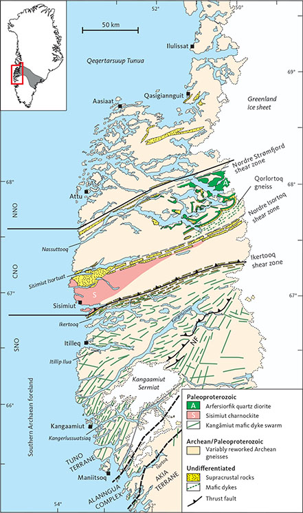
Fig. 1 Simplified geological map of West Greenland. Solid black lines indicate the internal subdivisions of the Nagssugtoqidian orogen, including the SNO (southern Nagssugtoqidian orogen), CNO (central Nagssugtoqidian orogen) and NNO (northern Nagssugtoqidian orogen; after Marker et al. 1995). Black dashed lines separate the Akia terrane, Alanngua complex and Tuno terrane (locations from Steenfelt et al. 2021) and correspond to the previously named Nordland, Alângua and Kangâmiut complexes, respectively, of Noe-Nygaard & Ramberg (1961a). Solid green lines indicate the Kangâmiut dykes investigated in this study from coastal regions (65°10’N to 67°N). North of Itillip Ilua and the Nagssugtoqidian front (NF), country rocks are largely Archaean gneisses and minor supracrustals, all variably to completely reworked during Nagssugtoqidian orogenesis. The trace of the NF is from Hageskov (1995, 1997, 1998) and Olsen (2000). Solid grey line: Aujassoq–Evighedsfjord shear zone (Allaart & Jensen 1979). Grey dashed lines: Nordre Strømfjord shear zone and Nordre Isortoq shear zone. Map based on information from Escher (1971), Allaart (1982) and Marker et al. (1995). The extent of the Nagssugtoqidian orogen across southern Greenland is shown in the inset map (grey shading).
In this contribution, we compile previously published studies of the Kangâmiut dyke swarm in West Greenland (65°10’N to 67°N), and present an extensive database including previously unpublished research, which allows us to refine our understanding of the tectonic and metamorphic evolution of the southern part of the Nagssugtoqidian orogen and its foreland.
After summarising the regional geology of the Nagssugtoqidian orogen and its southern foreland (Chapter 2), we describe in detail the Kangâmiut dykes and their host rocks between Maniitsoq in the south of the study area and Itillip Ilua (Itilleq) to the north (Chapters 3, 4), as well as the more intensely deformed and metamorphosed dykes and gneisses between Itillip Ilua and Ikertooq (Chapters 5, 6). The geochemical and metamorphic features of the Kangâmiut dykes are described in Chapter 7, thus providing a background for the metamorphic pressure and temperature calculations (Chapter 8). Lastly, we discuss and summarise the results and implications of this study. An overview of the place names referred to throughout this manuscript is provided in Fig. 2.
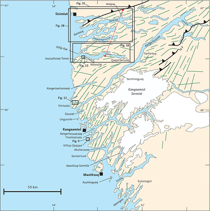
Fig. 2 The coastal region between Isortoq and Sisimiut showing place names mentioned in text and key figures. Green lines: Kangâmiut dykes. NF: Nagssugtoqidian Front. Red stippled line: profile on to which chemical data from dyke and country rock samples from Itillip Ilua to Ikertooq are projected in Fig. 97. Other symbols in Fig. 1.
2 Regional geology
The southern extent of the Nagssugtoqidian orogen in West Greenland was first described based on contrasting structural overprints on the extensive Kangâmiut dyke swarm and its host rocks. In a groundbreaking and influential paper, Ramberg (1949) noted that towards the north, the progressive structural reworking of the dykes and their Archaean host gneisses defined a locally sharp transition into a northern block he called the “Nagssugtoqides”, separated from the “Kangâmiut gneiss complex” to the south, where the gneisses and the dykes appeared unaffected by Nagssugtoqidian overprints.
Based on extensive reconnaissance mapping, Noe-Nygaard & Ramberg (1961a) compiled a geological map covering the coastal areas from 63°45N (just south of Nuuk) to 69°N (just north of Qasigiannguit, see Fig. 1). Their map shows the broad changes in orientation of the Kangâmiut dykes and the structural and metamorphic variations in the host gneisses. South of the Nagssugtoqidian, the Archaean gneisses are in granulite facies and farther north, these gneisses are, along with the dykes, thoroughly reworked in amphibolite facies. Later work (e.g. Escher et al. 1975, 1976a, b) further detailed the change in geometry of the Kangâmiut dykes (see Figs 3, 4) characterising and defining the southern structural limit of the Nagssugtoqidian orogen.
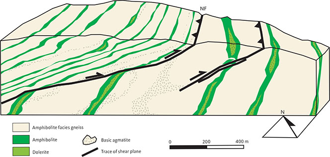
Fig. 3 The classic sketch from Escher et al. (1975) showing some of the pertinent features of the Nagssugtoqidian front (NF). The dramatic change in dip of dykes, thinning and shearing of the dykes and the reorientation of dykes into parallelism with the dominant gneiss fabric are indicated. Escher et al. (1975) based this sketch on field observations in Sarfartoq valley (14 km north of Kangaamiut Sermiat, Fig. 1). Notably, the ‘front’ is suggested to consist of an array of foreland-directed thrusts. Modified from Escher et al. (1975).
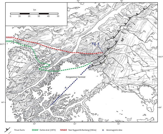
Fig. 4 Distribution and orientation of Kangâmiut dykes between Kangaamiut and Ikertooq. Modified from Escher et al. 1976b (their fig. 81). The transition across the Nagssugtoqidian front (NF) along Sarfartoq (middle of figure) is shown in Fig. 3. Based on field observations and aerial photo interpretation, this figure depicts the dramatic change in orientation of the dykes across the NF. It also highlights at least two distinct orientations of dykes in the foreland region (E–W, NNE–NE), mainly east of Kangaamiut Sermiat, and sporadically in the coastal regions south of Itillip Ilua. Large thrust symbols: thrusts maped by Hageskov (1995, 1997, 1998) and Olsen (2000) based on fieldwork in the inner Sarfartoq valley and helicopter reconnaissance along the NF. Their work describes the NF as a series of discrete foreland-directed ductile thrusts rather than one single thrust. Small thrust symbols: from the original sketch of Escher et al. (1976b), which often coincide with the larger thrust symbols. Dashed lines: traces of the NF proposed by Noe-Nygaard & Ramberg 1961a (red), Escher et al. 1975 (green) and based on aeromagnetic data (blue; e.g. Korstgård et al. 2006; see also Fig. 95).
More recently, the Nagssugtoqidian orogen has been subdivided into the southern Nagssugtoqidian orogen (SNO), the central Nagssugtoqidian orogen (CNO) and the northern Nagssugtoqidian orogen (NNO; Marker et al. 1995; Fig. 1), broadly coincident with respectively the “Ikertôq”, “Isortôq” and “Egedesminde” gneiss complexes of Ramberg (1949). The SNO is bound by the Ikertooq shear zone to the north and to the south by the frontal thrust zone that defines the southern margin of the Nagssugtoqidian orogen. The CNO extends up to the large-scale Nordre Strømfjord shear zone (Bak et al. 1975a, b) and includes tectonically interleaved Paleoproterozoic and Archaean gneisses and supracrustals in granulite facies. The NNO is less penetratively reworked than the SNO and CNO and displays a gradual transition towards the Paleoproterozoic Rinkian fold belt in the north (e.g. van Gool & Marker 2007; Thrane 2021).
Comparable observations in South-East Greenland (e.g. Bridgwater & Gormsen 1968; Kalsbeek 1989; Nutman et al. 2008; Kolb et al. 2016) suggest that the Nagssugtoqidian belt extends across Greenland and even into the Lewisian gneiss complex of NW Scotland (e.g. Myers 1987; Park 1995; Mason & Brewer 2004).
The Nagssugtoqidian orogen in West Greenland is dominated by Archaean gneisses and supracrustals with some Paleoproterozoic intrusives and supracrustals, all variably deformed and metamorphosed during the Proterozoic. The main crust building episode occurred at 2870–2810 Ma and was closely followed by penetrative reworking at 2790–2690 Ma (e.g. Kalsbeek & Nutman 1996; Connelly & Mengel 2000; Connelly et al. 2006). The oldest components identified within the Nagssugtoqidian orogen so far are the 3177 Ma Qorlortoq gneisses (McIntyre et al. 2021; Fig. 1). A summary of published geochronological data document the protracted and complex history of magmatism and metamorphism culminating at c. 2850–2750 Ma (Fig. 5; Table 1). Minor Archaean intrusive activity is recorded in the southern part of the orogen at c. 2500 Ma (Kalsbeek & Nutman 1996; Connelly et al. 2000). Deformation and metamorphism of these rocks appear to have virtually ceased by c. 2400 Ma.
| Dyke name | Sample no. | Location (as named in source) | Age (Ma) | Method | Type | Source |
| Maniitsoq to Itilleq: | ||||||
| Kangâmiut dyke | 430909 | Inner Søndre Strømfjord | 1697 ± 15 | 40Ar-39Ar (Amp) | metamorphic | Willigers et al. 1999 |
| Kangâmiut dyke | 414915 | Eastern Ikertooq shear zone | 1740 ± 15 | 40Ar-39Ar (Amp) | metamorphic | Willigers et al. 1999 |
| Kangâmiut dyke | 431205 | Inner Ikertooq | 1742 ± 14 | 40Ar-39Ar (Amp) | metamorphic | Willigers et al. 1999 |
| Kangâmiut dyke | 430605 | Inner Søndre Strømfjord | 1745 ± 15 | 40Ar-39Ar (Amp) | metamorphic | Willigers et al. 1999 |
| Kangâmiut dyke | 414473 | Maligiaq | 1756 ± 13 | 40Ar-39Ar (Amp) | metamorphic | Willigers et al. 1999 |
| Kangâmiut dyke | 430261 | N of Hamborgerland | 1840 ± 80 | Mineral Sm-Nda | metamorphic | Stecher et al. 1998 |
| Kangâmiut dyke (podded) | 431223 | N of Hamborgerland | 1863 ± 13 | 40Ar-39Ar (Amp) | metamorphic | Willigers et al. 1999 |
| Kangâmiut dyke (podded) | 431223 | N of Hamborgerland | 1873 ± 13 | 40Ar-39Ar (Amp) | metamorphic | Willigers et al. 1999 |
| Kangâmiut dyke | 158078 | NNW of Kangaamiut | 1950 ± 60 | Rb-Sr (WR) | igneous | Kalsbeek et al. 1978 |
| Kangâmiut dyke (ENE) | 448916 | Simiutak, mouth of Søndre Strømfjord | 1981 ± 18 | 40Ar-39Ar (Amp) | metamorphic | Willigers et al. 1999 |
| Kangâmiut dyke (E-W) | 448933 | Kangerluarsugssuaq | 1981 ± 26 | 40Ar-39Ar (Amp) | metamorphic | Willigers et al. 1999 |
| Kangâmiut dyke (ENE) | 431264 | Mouth of Søndre Strømfjord | 2013 ± 14 | 40Ar-39Ar (Amp) | igneous? | Willigers et al. 1999 |
| Kangâmiut dyke (ENE)) | 448915 | Kangerluarsugssuaq | 2021 ± 13 | 40Ar-39Ar (Amp) | igneous? | Willigers et al. 1999 |
| Kangâmiut dyke | 87777 | N of Hamborgerland | 2021 ± 4 | U-Pb (Zrn) | igneous | Nilsson et al. 2019 |
| Kangâmiut dyke (undeformed) | 431229 | Inner Itilleq | 2028 ± 29 | 40Ar-39Ar (Amp) | igneous? | Willigers et al. 1999 |
| Kangâmiut dyke | 413794 | Outer Itilleq | 2036 ± 5 | U-Pb (Zrn) | igneous | Nutman et al. 1999 |
| Kangâmiut dyke | 158078 | NNW of Kangaamiut | 2046 ± 8 | U-Pb (Zrn) | igneous | Nutman et al. 1999 |
| Kangâmiut dyke | 430248 | N of Hamborgerland | 2048 +4/–2 | U-Pb (Zrn) | igneous | Connelly et al. 2000 |
| Kangâmiut dyke | 87777 | N of Hamborgerland | 2478 ± 7b | 40Ar-39Ar (Amp) | igneous? | Nilsson et al. 2019 |
| Kangâmiut dyke | 87777 | N of Hamborgerland | 2492 ± 7b | 40Ar-39Ar (Amp) | igneous? | Nilsson et al. 2019 |
| Kangâmiut dyke | 87777 | N of Hamborgerland | 2528 ± 25b | 40Ar-39Ar (Amp) | igneous? | Willigers et al. 1999 |
| Paamiut to Nuuk: | ||||||
| MD2 (NE) | 511577 | Sermilik, E of Paamiut | 2209 ± 5 | U-Pb (Bdy) | igneous | Nilsson et al. 2013 |
| MD3 | 468749 | Sermilik | 2029 ± 3 | U-Pb (Bdy) | igneous | Nilsson et al. 2010 |
| MD3 | 515830 | Inner Bjørnesund | 2040 ± 3.1 | U-Pb (Bdy) | igneous | Nilsson et al. 2010 |
| MD3 | 515805 | Ravn Storø | 2050 ± 2 | U-Pb (Bdy) | igneous | Nilsson et al. 2010 |
| MD3 (E-W) | 508242 | Inner Bjørnesund | 2053 ± 2 | U-Pb (Bdy) | igneous | Nilsson et al. 2013 |
| MD3 (N-S) | 508210 | Inner Bjørnesund | 2049 ± 6 | U-Pb (Bdy) | igneous | Nilsson et al. 2013 |
| MD3 (WNW) | 508213 | Inner Bjørnesund | 2042 ± 2 | U-Pb (Bdy) | igneous | Nilsson et al. 2013 |
| BN (N-S) | Isukasia | 2214 ± 10 | U-Pb (Zrn) | igneous | Nutman et al. 1995 | |
| E-W dykes | 508214 | Inner Bjørnesund | 2365 ± 2 | U-Pb (Bdy) | igneous | Nilsson et al. 2013 |
| E-W dykes | 508201 | Grædefjord | 2374 ± 4 | U-Pb (Bdy) | igneous | Nilsson et al. 2013 |
| aPlagioclase, amphibole and garnet (metamorphic minerals). bindicating excess Ar, hence geologically meaningless (Nilsson et al. 2019). Amp: amphibole. Bdy: baddeleyite. WR: whole rock. Zrn: zircon. Location names as per source: Søndre Strømfjord (Kangerlussuaq), Hamborgerland (Sermersuut), Kangerluarsugssuaq (Kangerluarsussuaq, Sisimiut), Itilleq (Itillip Ilua), Bjørnesund (Allumersat), Ravn Storø (Takisup Qeqertarsua), Grædefjord (Kangerluarsussuaq (Nuuk)). | ||||||
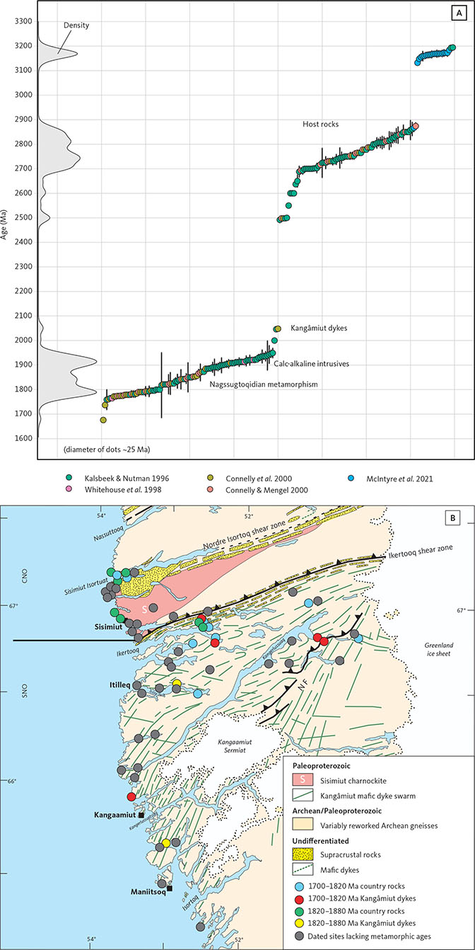
Fig. 5 Key published age data from the Nagssugtoqidian orogen. A: 207Pb–206Pb age data measured on zircon grains by various methods (sensitive high resolution ion microprobe - SHRIMP; Thermal ionization mass spectrometry - TIMS; laser ablation split stream - LASS, inductively coupled plasma-mass spectroscopy - ICP-MS). Reported 2σ standard deviation (SD) for each analysis is shown. Density curve along y-axis illustrates the distribution of the 199 ages. Discrete events shown by data clusters are annotated. Data from Kalsbeek & Nutman (1996), Whitehouse et al. (1998), Nutman et al. (1999), Willigers et al. (1999), Connelly & Mengel (2000), Connelly et al. (2000), McIntyre et al. (2021). Key published age data from the Nagssugtoqidian orogen. B: Regional map showing the distribution of all dated samples. The samples with metamorphic dates are indicated by the specific metamorphic period recorded. Abbreviations in Fig. 1.
Accompanying crustal extension and rifting, the mafic Kangâmiut dyke swarm (Fig. 1) intruded at 2045–2021 Ma (Kalsbeek & Nutman 1996; Nutman et al. 1999; Connelly et al. 2000; Nilsson et al. 2019). The first isotopic dating accomplished on mafic Kangâmiut dykes was published by Kalsbeek et al. (1978). Thirteen samples from two dykes produced a Rb–Sr isochron age of 1950 ± 60 Ma. This date was interpreted to be the emplacement age of those two dykes and was assumed to be representative for all Kangâmiut dykes. Later, Nutman et al. (1999) undertook a U–Pb zircon age study of two Kangâmiut dykes and detrital zircons from metasediments throughout the Nagssugtoqidian region. The first dyke (158078), which was also included in the earlier Rb-Sr study, produced an age of 2046 ± 8 Ma whereas the second dyke (413794) gave an age of 2036 ± 5 Ma. This led to the conclusion that the entire Kangâmiut dyke swarm was emplaced at c. 2040 Ma. At the same time, Willigers et al. (1999) published an extensive 40Ar–39Ar study that included amphibole analyses from 18 dyke samples. They, too, concluded that the primary emplacement age was c. 2040 Ma. They also observed younger ages that occur in two clusters with means of 1857 ± 14 Ma and 1736 ± 20 Ma (Fig. 6) and were interpreted to represent “post-peak metamorphic cooling”. A conventional U–Pb zircon date was obtained by thermal ionization mass spectrometry (TIMS) on a dyke by Connelly et al. (2000). Their result of 2048 +4/–2 Ma was considered consistent with previous results. Most recently, Nilsson et al. (2019) reported a U–Pb zircon (TIMS) analysis from one additional sample (87777) to be 2021 ± 4 Ma. These results are further summarised in Fig. 6 and Table 1.
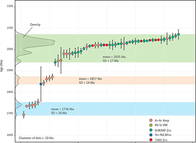
Fig. 6 All published dates for Kangâmiut dykes, sorted by age. Diameter of dots c. 10 Ma. Also shown are the computed means and 1 SD for the apparent clusters in the ranges c. 1760–1700 Ma (blue shading), c. 1870–1840 Ma (orange shading) and c. 2070–1940 Ma (green shading). Density curve is shown along the y-axis. The reported 2 SD for each age is shown as vertical bars. Data from Kalsbeek et al. (1978), Kalsbeek & Nutman (1996), Stecher et al. (1998), Nutman et al. (1999), Willigers et al. (1999), Connelly et al. (2000) and Nilsson et al. (2019). Ar–Ar Amp: 40Ar–39Ar plateau ages from amphiboles. Rb–Sr WR: whole-rock isochron age from two Kangâmiut dykes. SHRIMP Zrn and TIMS Zrn: 207Pb–206Pb ages from zircons by SHRIMP or TIMS. Sm–Nd Mins: mineral isochron age based on amphibole, garnet and plagioclase from Kangâmiut dykes.
The dykes form a dense, generally NNE-trending regional suite of Fe-rich tholeiites, extending northwards from Isortoq (Søndre Isortoq) for at least 200 km (Fig. 1). The dykes have been found in the SNO and the southernmost parts of the CNO. Similar discordant mafic dykes of possible Paleoproterozic age are found in the northernmost part of the CNO and the NNO (e.g. Sørensen 1970, 1971; Glassley & Sørensen 1980; Mengel 1983; Àrting 2004; Sørensen et al. 2006). However, these dykes have not been dated and their relationship with the Kangâmiut dyke swarm is currently unknown. In addition to the Kangâmiut dykes, the Precambrian in West and South-West Greenland is cut by several other swarms of Proterozoic mafic dykes. Some of these are listed together with their referenced ages in Table 1. It is notable, that the meta-doleritic, 2053–2029 Ma MD3 dykes of South-West Greenland are broadly the same age as the Kangâmiut dykes, despite occurring 200–300 km farther south. An important inference from this is that the extensional tectonic regime responsible for the emplacement of the Kangâmiut dykes was clearly not an isolated phenomenon in the western Greenland crust c. 2000 Myr ago.
Minor amounts of juvenile, intrusive material was added to the crust between 1950 Ma and 1870 Ma (‘A’ and ‘S’ in Fig. 1; Kalsbeek et al. 1987; Kalsbeek & Nutman 1996; Connelly et al. 2000). Located along the CNO–NNO boundary, the field relationships and arc-like calc-alkaline chemical signatures of the Arfersiorfik quartz diorite intrusion (‘A’ in Fig. 1) was suggested by Kalsbeek et al. (1987) to indicate the presence of a cryptic suture along the Nordre Strømfjord shear zone (Fig. 1). More recent work (Sørensen et al. 2006; Glassley et al. 2014) has further substantiated the presence of such a fundamental tectonic boundary in this part of the Nagssugtoqidian orogen.
Lastly, multi-phase collisional orogeny between 1873 Ma and 1775 Ma (Kalsbeek & Nutman 1996; Willigers et al. 1999; Connelly et al. 2000; van Gool et al. 2002) created the Nagssugtoqidian orogen. In this study, we focus on the development of the southern part of the orogen and its foreland.
The Archaean gneisses south of the Nagssugtoqidian orogen (referred to as the “Kangâmiut gneiss complex” of Ramberg 1949) have been characterised by a wealth of field, chronological and isotopic data and the area has been further subdivided into terranes (sensu Coney et al. 1980; Nelson et al. 2013). For a summary of the developing nomenclature, see e.g. Friend & Nutman (2019) and Steenfelt et al. (2021).
Detailed aspects of the southern structural front were described in Escher et al. (1975). A well-exposed section along Sarfartoq valley (Fig. 3) shows the dramatic change in dyke orientation characterising the southern Nagssugtoqidian Front (NF), especially in the areas north-east of the ice cap Kangaamiut Sermiat (Fig. 4). West of the ice cap, the transition is less well defined and the change in orientation of the Kangâmiut dykes is more gradual.
The continued trace of the Southern NF west of Kangaamiut Sermiat is still a matter of debate. While the structures east of the ice cap are fairly well defined by networks of foreland-directed thrusts, farther west, such structures have not been observed. One reason is likely the inaccessibility of the area between Itillip Ilua and the area south of the mouth of Kangerlussuaq (Søndre Strømfjord). Figure 4 shows three examples of proposed continuation of the NF. On earlier maps (Noe-Nygaard & Ramberg 1961a), a tentative continuation of the NF was sketched through Itillip Ilua. However, this was before the Itilleq shear zone was known to predate the Nagssugtoqidian orogen by more than 600 Myr. Escher et al. (1975) proposed an arcuate boundary that also ended up near Itillip Ilua (Fig. 4). The aeromagnetic anomalies show a boundary that appears to continue towards the south-west (Fig. 4). It is possible that more distributed shortening across the NF was accommodated in the ductile regime in the coastal regions where deeper crustal levels are exposed, and that shortening at the shallower crustal levels exposed towards the Greenland ice sheet manifested itself as recognisable thrusts. Regardless of the favored interpretation, any model is, at present, highly speculative due to the lack of structural observations in the critical, but highly inaccessible areas west of Kangaamiut Sermiat.
While the emplacement of the Kangâmiut dykes is now known to pre-date the Nagssugtoqidian deformation and metamorphism by at least 150 Myr, the relationship between dyke intrusion and pre-existing structures is still a topic of some debate. In the Inussuttusup Tunua area (Anders Olsen Sund), Escher et al. (1975) and Jack (1978) argued that the dykes were emplaced into an overall contractional environment. The NE-trending Kangâmiut dykes occurred typically in sinistral shear zones, whereas E–W- to ESE–WNW-trending dykes were located in dextral shear zones striking c. 100°. This conjugate set of shear zones was interpreted to represent a NNW–SSE-orientated maximum horizontal stress, and the authors further argued, based on field interpretations, that dilational opening took place parallel to the minimum horizontal stress direction (ENE–WSW). The conjugate set of fractures was believed to partly pre-date dyke emplacement and to have been formed partly or reactivated by elevated hydrostatic magma pressures during dyke emplacement. Nash (1979a, b) suggested that similar field relationships could be seen between pre-existing structures, dyke emplacement and orientation of the accompanying palaeo-stress system in the western part of Itillip Ilua. Recent dating of Kangâmiut dykes have, however, necessitated alternative models for the observed structural relationships (see Section 3.1).
Based on field observations in the area east of Kangaamiut Sermiat, Hageskov (1995, 1997, 1998) and Olsen (2000) argued that the Kangâmiut dyke swarm did not intrude along pre-existing faults or shear-zones, in contrast to the syn-intrusive conjugate shear system proposed above. Rather, they argued that during emplacement, the dykes generated their own extensional fractures opening perpendicular to both local and regional minimum horizontal palaeo-stress fields.
The age and nature of the metamorphic overprint displayed by the Kangâmiut dykes are also a topic of discussion. Several earlier descriptions state that in the orogenic foreland to the south, dykes are generally unmetamorphosed and undeformed (i.e. ‘fresh’) and that it is only north of Itillip Ilua that dykes display any significant metamorphism (e.g. Ramberg 1949; Noe-Nygaard & Ramberg 1961b). In apparent contrast, works by Windley (1970) at Maniitsoq and Jack (1978) at Inussuttusup Tunua, just south-west of Itillip Ilua, describe metamorphic overprints on the igneous mineral assemblages of the dykes. However, these studies attributed the overprints to late-magmatic features associated with so-called ‘autometamorphic’ mineral growth during elevated temperatures, immediately following emplacement. Subsequently, Korstgård (1980) interpreted all metamorphic overprints between Itillip Ilua and Ikertooq as being of Nagssugtoqidian age. More recent reconnaissance work between Itillip Ilua and Maniitsoq by the Danish Lithosphere Centre (e.g. Mengel et al. 1997, 1998) mapped the extent of such metamorphic overprints to >100 km south of Itillip Ilua, and – albeit based on a limited data set – also argued that this metamorphic overprint was of Nagssugtoqidian age. Dating of metamorphic minerals (Willigers et al. 1999; Stecher et al. 1998) supported this suggestion.
3 Dykes and country rocks from Maniitsoq to Maligiaq
In this chapter we outline the field relations of the dykes and their host rocks in the study area. From Maniitsoq to Itillip Ilua (Figs 1, 2; Section 3.1), the dykes and their host gneisses suffered negligible structural overprints due to the Nagssugtoqidian orogeny, whereas we will argue that the dykes record a range of metamorphic effects. In contrast, between Itillip Ilua and Maligiaq (Figs 1, 2; Section 3.2), the Nagssugtoqidian structural and metamorphic overprints are pronounced and penetrative in both dykes and their country rocks.
Several generations of dykes occur in the area studied here. By far the volumetrically dominant is a suite of NNE–NE-trending mafic dykes, which are traditionally considered to belong to the main Kangâmiut dyke swarm, and which are the main focus of the present study. E–W-trending dykes occur throughout but are much less common. Mayborn (2000) identifies two compositionally different suites of E–W dykes: orthopyroxene-bearing “OB dykes” and plagioclase-phyric “PP dykes” and finds that the main Kangâmiut dyke swarm generally crosscuts both types. Similarly, Windley (1970) and Jack (1978) describe E–W dykes from the Maniitsoq and Inussuttusup Tunua areas, respectively (Sections 3.1.2 and 3.1.5) predating the main Kangâmiut dyke swarm.
It is important to emphasise that there are currently no age constraints on these potentially different E–W-trending dykes. Consequently, we will use the term ‘Kangâmiut dykes’ to describe them all while acknowledging that further studies may well suggest the existence of temporally different intrusive events.
3.1 Dykes and country rocks from Maniitsoq to Itillip Ilua
The regional extent of the Kangâmiut dyke swarm is well-known from early reconnaissance work (e.g. Noe-Nygaard & Ramberg 1961a) and members of the swarm can be found intruding Archaean gneisses as far south as c. 10 km south of the mouth of Isortoq (Fig. 2).
3.1.1 Isortoq to Maniitsoq
Around Isortoq, host rocks are polyphase tonalitic to granodioritic gneisses in amphibolite facies (Fig 7A, B), locally hosting concordant supracrustal and mafic units. Planar fabrics in the gneisses are generally subvertical and NE-striking. Kangâmiut dykes are typically less than a few metres wide with sharp contacts along which occur intricate small-scale intrusive features, bridges, and chilled contact zones (Fig 8A–C). The dykes generally show right-stepping asymmetry (Fig. 8A). Coarse-grained leucocratic pegmatites, with conspicuous black feldspars (Fig. 7B), truncate the gneissic host rocks and are themselves cut by Kangâmiut dykes. Alanngua (Fig. 2) appears to mark the southernmost occurrence of Kangâmiut dykes. The c. 3 Ga Finnefjeld orthogneiss complex (Gardiner et al. 2019) occurs immediately east of Alanngua and was not found to be intruded by Kangâmiut dykes.
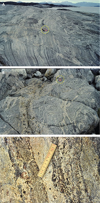
Fig. 7 Field examples of dykes. A: Archaean grey tonalitic to granodioritic polyphase layered gneisses in amphibolite facies, Alanngua (view towards SSE). Notebook (in yellow dashed circle) is 11 x 18 cm. B: Same as panel A but showing detail of discordant, coarse-grained, undeformed plagioclase-rich pegmatite. C: Migmatised metapelitic unit in granulite facies gneisses from north-east Sermersuut. Large reddish garnets and smaller brownish orthopyroxenes are visible in coarser-grained layers. Scale is 10 cm.
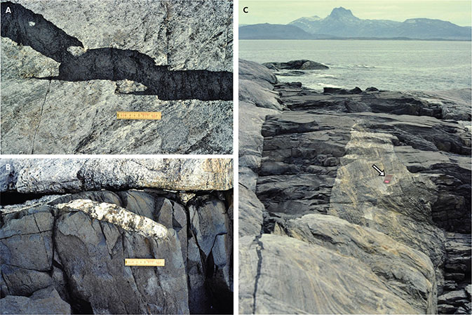
Fig. 8 Field examples of dykes. A: 10 cm wide, discordant, undeformed Kangâmiut dyke, hosted by Archaean grey tonalitic gneisses in amphibolite facies. Dyke shows delicate intrusive features (hooks, bridges, bayonets) consistent with right-stepping offsets, Alanngua. Scale is 10 cm. B: Detail of the margin of a 50 cm wide Kangâmiut dyke that cuts granulite facies host gneisses discordantly. A left-stepping offset is indicated by a broken bridge. Subtle drag folding of possible cooling joints within the dyke’s horn is consistent with minor sinistral displacement along this margin. North-east Sermersuut. Scale is 10 cm. C: A 4 m wide Kangâmiut dyke that discordantly cuts the layering of grey, tonalitic gneisses in amphibolite facies. Narrow abandoned fracture in left foreground shows overall left-stepping intrusion geometry. Sulussugut (Finnefjeld) in background. Alanngua. Notebook at arrow is 11 x 18 cm.
From Isortoq and towards Maniitsoq (Fig. 2), the host gneisses are in granulite facies, as shown by orthopyroxene in leucocratic patches in both gneisses and in schistose mafic and felsic supracrustals (Fig. 7C). Overall, the planar fabrics in the gneisses around Maniitsoq are subvertical with variable strikes reflecting large-scale folding. In this area, the Kangâmiut dykes trend NNE and, like further south, preserve intrusive features and show right-stepping asymmetry. Locally, a weak margin-parallel foliation is developed in the dykes. On the eastern side of Sermersuut (Hamborgerland; Fig. 2), dykes cut across migmatised supracrustals and display subtle sinistral drag within their margins. Also notable is that dykes here show left-stepping intrusion geometries as opposed to the dominantly right-stepping dykes farther south (Fig. 8B).
Along the north shore of Isortoq, subtle metamorphic overprints on the igneous dyke mineralogy are visible in outcrop, as igneous clinopyroxenes are partially replaced by amphiboles and garnets are often observed.
The proposed extension of the Aujassoq–Evighedsfjord shear zone (Allaart & Jensen 1979) projects through the Kuulinnquaq islands, just a few km SE of Maniitsoq (Fig. 2; cf. 1:500 000 Geological map, Allaart 1982). On one of these, an island c. 100 m across, the shear belt is characterised by alternating panels of protomylonite, schistose zones and normally foliated gneiss. Their axial planar foliations are subvertical and strike NE, and lineations – defined by amphibole and aggregates in mafic pods – plunge shallowly to moderately SW. All observed kinematic indicators (delta-clasts) on subhorizontal surfaces indicate sinistral shear. Farther north-east of Kuulinnquaq, across smaller islands and along the shores of Maniitsup Sermilia (Fig. 2), steeply dipping gneissic structures are consistently NE-trending and define a distinct zone of parallel planar fabrics. Allaart & Jensen (1979) noted that farther inland, dykes appear unaffected by the linear belt, thus suggesting a pre-dyke age for this major structure.
Older dykes are occasionally also observed. One mafic, discordant and overall E–W-trending dyke with 1–2 cm black feldspar phenocrysts is folded, contains the same planar NE-striking fabric as the country gneisses and is assumed to be of pre-Kangâmiut age. Just NE of Maniitsoq, an ESE-trending, 2 m wide, brown, discordant and vesicular dyke, with a pronounced sidewall-parallel layering, was noted. Its relationship with the generally NNE-trending Kangâmiut dykes was, however, not exposed.
3.1.2 Maniitsoq to Kangerlussuatsiaq
Between Maniitsoq and the Kangerlussuatsiaq (Evighedsfjord), dykes maintain their NNE trend but are wider and the swarm appears overall denser. Figure 9 shows a typical occurrence of NNE-trending dykes across parts of an island south of the mouth of Kangerlussuatsiaq.
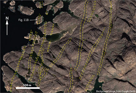
Fig. 9 A dense swarm of NNE-trending Kangâmiut dykes (yellow dashed lines) on the island Itilliup Qaqqaa at the mouth of Kangerlussuatsiaq. Key dykes have been outlined for clarity. The dyke slightly right of the centre of the image (arrow) is c. 40 m wide. Layering in host gneisses strike ENE. Image from Google Earth (centre of image at 65°44’10N, 53°14’30W). Location in Fig. 2.
Host gneisses and associated supracrustal units are all in granulite facies and exhibit folding at various scales – unlike those farther south. There are also some structurally simpler granitic intrusions, which are cut by Kangâmiut dykes and assumed to be of late Archaean age.
In the area around Maniitsoq, Windley (1970) finds that the NNE-trending Kangâmiut dykes truncate two older dyke sets as (1) a NE-trending set of black ophitic dolerites, and (2) a SE-trending set of ‘blue’ porphyritic dolerites. In addition, the Kangâmiut dykes are themselves cut by SE-trending, brown-red and vesicular dykes. The exact ages of these other dykes are not known.
The wider Kangâmiut dykes are often compositionally zoned, from fine-grained and ophitic to sub-ophitic chilled margins, to gradually coarser grained and plagioclase-rich central parts (Fig. 10A). Garnets are common in the more felsic centres along with amphibole and plagioclase. In a detailed study of dykes between north and north-east of Sermersuut (Fig. 2), it was proposed that the largely symmetrical zoning of the larger dykes was caused by a single protracted intrusive event (Windley 1970). This event led to earlier magma injections that chilled rapidly and preserved an igneous mineralogy, whereas subsequent pulses involved a more felsic (and hydrous) magma, which led to the metamorphic garnet-amphibolites.
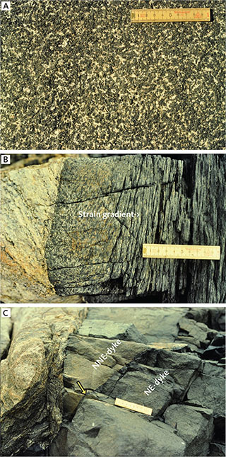
Fig. 10 Field examples of dykes. A: Coarse-grained garnet-bearing amphibolite from centre of c. 40 m wide zoned dyke. Akuliaruseq, NE of Sermersuut (location in Fig. 2). Scale is 10 cm. B: Margin of 1.5 m wide NNE-trending Kangâmiut dyke, showing localised foliation development in 0.2–0.5 m wide margin-parallel zones. North shore of Tunu (Hamborgersund) north of Sermersuut. Scale is 10 cm. C: A 30 m wide NNE-trending Kangâmiut dyke cut by 0.5 m wide NE-trending dyke. Thin chilled margin in NE-trending dyke (arrow). Tinuteqisaaq, a small island on south side of the mouth of Kangerlussuatsiaq. Scale is 10 cm.
The dykes between Maniitsoq and Kangerlussuatsiaq exhibit a range of metamorphic overprints observable in outcrop, including amphiboles replacing clinopyroxenes and the rare to widespread presence of garnets.
3.1.3 Kangerlussuatsiaq to Simiutaq
At the mouth of Kangerlussuatsiaq (Fig. 2), there are several examples of cross-cutting dykes (Figs 10C, 11A). On one of the smaller islands, an E–W dyke is cut by a NE-trending dyke with a chilled margin against the earlier dyke reflecting the relative age relationships seen elsewhere (Fig. 11B).

Fig. 11 Field examples of dykes on Itilliup Qaqqaa, a small island on the south side of the mouth of Kangerlussuatsiaq. A: Contact (yellow dashed line) between a 70 m wide, NNE-trending coarser-grained Kangâmiut dyke (beneath) and a later, finer-grained, NE-trending dyke (above). The later dyke has a subtle, chilled margin against the coarse-grained dyke and displays consistent left-stepping intrusion geometry on horizontal surfaces. Scale is 10 cm. B: 30 m wide NNE-trending Kangâmiut dyke, cut by NE-trending c. 0.5 m wide dyke located in the north-western corner of Itilliup Qaqqaa (location in Fig. 9).
Between Kangaamiut and Simiutaq, at the mouth of Kangerlussuaq, overall dyke trends begin to subtly bend from NNE towards NE (Fig. 2) as the swarm also appears slightly denser. Host gneisses are all in granulite facies, with planar fabrics with varying strikes and moderate to steep northerly to westerly dips. Ungusivik island (midway between Kangaamiut and Simiutaq; Fig. 2) is where one of the first dated Kangâmiut dykes was collected (age presented by Kalsbeek et al. 1978). The 1950 ± 60 Ma Rb–Sr age (see also Chapter 9) was obtained from samples on Ungusivik and at Sisussat (Fiskemesterens Havn), on the central, leucocratic portions of NNE-trending, c. 60 m wide composite dykes, cutting granulite facies gneisses. Later, Nutman et al. (1999) obtained a 2046 ± 8 Ma U–Pb zircon SHRIMP age from the dyke on Ungusivik. The dyke has a well-developed, steep, margin-parallel foliation, with both SW- and NE-plunging stretching lineation defined by amphibole aggregates. Kinematic indicators on horizontal surfaces show consistent sinistral shear. Metamorphic garnets are developed in most dykes, particularly in the leucocratic centres of wider dykes. The same range of metamorphic overprints can also be found throughout the coastal dyke exposures between Kangaamiut and Simiutaq.
At Sisussat, just south of Simiutaq (Fig. 2), the second of the two dykes dated by Kalsbeek et al. (1978) was sampled. At this locality, the dykes are up to 60 m wide, typically composite with leucocratic, garnet-bearing centres. They are overprinted by steeply dipping and NNE-striking foliated zones containing shallow SSW-plunging stretching lineation, defined by amphibole aggregates. On horizontal surfaces, kinematic indicators always show sinistral asymmetry.
On Simiutaq island, Kangâmiut dykes are ubiquitous and trend systematically 25–30°. The dykes are typically up to 40–60 m wide and occur about every 500–1000 m. Figure 12 shows the north coast of Simiutaq and the regular spacing of Kangâmiut dykes as well as an earlier formed 70 m wide E–W-trending dyke (Fig. 13A). Host rocks are granulite facies gneisses with abundant mafic inclusions and layers. The dykes have preserved a range of delicate, brittle intrusive features, such as bayonets (Fig. 13B). Where these are developed, dykes are left-stepping, similar to what was observed along the coast from the north shore of Sermersuut and farther north. The metamorphic overprints observed here are the same as farther south: amphiboles replacing clinopyroxenes and rare to widespread garnets in leucocratic parts of the dyke.
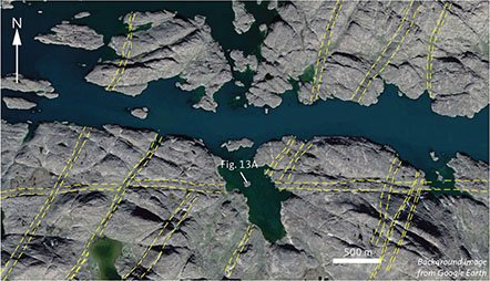
Fig. 12 Satellite view of a 70 m wide E–W dyke, cut by a swarm of NNE-trending Kangâmiut dykes. At this location, NNE dykes occur approximately every 400–500 m and are up to 40–50 m wide. Some of the larger dykes are outlined (yellow dashed lines). North shore of Simiutaq island, in the mouth of Kangerlussuaq. Image from Google Earth. Small island in centre of image is at 66°05’16N, 53°33’10W. Location in Fig. 2.
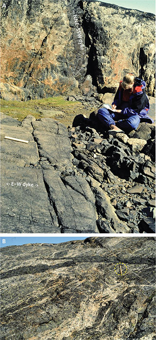
Fig. 13 Field examples of dykes on Simiutaq island, at the mouth of Kangerlussuaq. A: 70 m wide E–W dyke cut by 0.5 m NNE-trending Kangâmiut dyke. Location in Fig. 12. B: Discordant NNE–NE-trending Kangâmiut dyke showing left-stepping intrusion features. Host rocks are heterogeneous, migmatised amphibolite facies gneisses. North shore of Simiutaq. Hammer (in yellow dashed circle) is 40 cm long.
Entering the Nagssugtoqidian frontal thrust zone from Kangerlussuaq, the curvature of the dyke swarm becomes increasingly apparent. Only 30–40 km east of Simiutaq, the dykes mainly strike NE to ENE parallel to the Kangerlussuaq fjord, and dip gently NW to NNW (Figs 4, 14). At Serminnguaq (Fig. 4), Hansen (1989) notes that the host rocks are amphibolite facies granodioritic gneisses and that metamorphic overprints on the dykes can be seen in outcrop. Further into Kangerlussuaq, opposite Sarfartoq (Fig. 2), Mayborn (2000) found that dykes are generally foliated but preserve intrusive relationships with amphibolite facies gneisses that are interpreted as reworked and retrogressed Archaean granulite facies gneisses (Fig. 14).
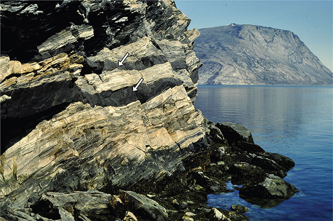
Fig. 14 View ENE from the north shore of Kangerlussuaq towards Sarfartoq (north wall of Sarfartoq valley in the background). Centre of image shows a pair of 1 m wide Kangâmiut dykes (indicated by arrows) thoroughly rotated into parallelism with NNW-dipping layering in deformed amphibolite facies host gneisses. Locally, the discordant nature of the dykes is preserved (e.g. at tip of the uppermost arrow).
3.1.4 Kangerluarsussuaq
Further north along the outer coast from Simiutaq, the Kangerluarsussuaq fjord (Fig. 2) offers an excellent 25 km E–W-orientated section through the dyke swarm. Mayborn (2000) investigated this section in detail, and the following description is based on that work. Dykes trend on average 30° and vary in width from less than 1 m to 140 m. Excluding the widest (140 m) and thinnest (0.4 m), the mean width is c. 30 m. The host gneisses are in granulite facies throughout. The compositional layering in the gneisses generally strike in a north-westerly direction with moderate to steep south-westerly dips. Thinner dykes and the margins of wider dykes only show incipient amphibole- and garnet-growth. In contrast, wider dykes display a zoning similar to that described above and by Windley (1970), with leucocratic centres showing strong foliation and a completely recrystallised mineral assemblage of plagioclase, amphibole, garnet and biotite.
Inside a 140 m wide dyke, the central leucocratic component appears to intrude the marginal, less altered parts of the dyke as late-stage metamorphic epidote-quartz-feldspar veins (Mayborn 2000). Similar features were observed in the wide dyke south of Simiutaq (Section 3.1.3). A NE-trending, orthopyroxene-bearing dyke shows the same metamorphic overprints as ‘typical’ Kangâmiut dykes, while an E–W-trending, plagioclase-phyric 2 m wide dyke was observed near the mouth of Kangerluarsussuaq and showed only minor metamorphic overprints.
3.1.5 Inussuttusup Tunua area
From the stretch of coast between Kangerluarsussuaq and Itillip Ilua, most observations come from the work of Jack (1978) in the Inussuttusup Tunua area (Fig. 2). The country rocks are granulite facies tonalitic to granodioritic gneisses, with only minor supracrustal material, notably in the NE Inussuttusup Tunua area. Here, mixed supracrustal units and gneisses occur in the core of a 10 km long by 3 km wide NE-trending structural basin, surrounded by reworked or retrogressed gneisses in amphibolite facies (Davidson 1978; Jack 1978). The north-western half of the Inussuttusup Tunua area is characterised by flat-lying structures, only interrupted in the south-west by a c. 2 × 4 km dome structure, rimmed by supracrustals and cored by granite (Davidson 1978; Jack 1978). The dykes truncate all of the above units with dominant trends of 30–35° in the southern part of the Inussuttusup Tunua area and up to 45° in the north, towards the mouth of Itillip Ilua (Fig. 15).
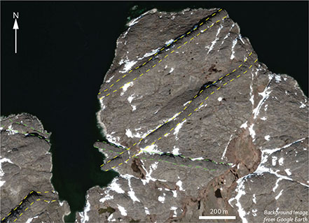
Fig. 15 Satellite view of NE-trending dykes cutting an ESE-trending dyke on the north coast of Inussuttusup Tunua. Individual dykes in both sets are c. 35–40 m wide in this image. Key dykes are outlined (yellow dashed lines) for clarity. Image from Google Earth. Intersection of dykes located at 66°31’34N, 53°27’10W. Location in Fig. 2.
In a detailed study of the dykes in the area, Jack (1978) described several sets. Type 1 are smaller (<10 m) NNE-trending dykes. Type 2 are larger (>10 m) and substantially more abundant NE-trending dykes. Type 3 are E–W-trending doleritic dykes and type 4 are E–W-trending black feldspar porphyritic dykes. Type 4 dykes appear to be the earliest, whereas cross-cutting relationships between types 1, 2 and 3 suggest that these are largely contemporaneous. The overall density of dykes increases from north-west to south-east in the area studied.
Jack (1978) further found that basement rocks are cut by two sets of conjugate shear zones, with a 100–110°-trending set of narrow and discrete dextral cataclastic zones and an NE-trending set of wider and sinistral ductile shear zones. Most dykes typically show apophyses and bayonets that display a systematic sense of asymmetry for individual swarms (figs 2.5, 2.6 in Jack 1978), where E–W-trending dykes show left-stepping offsets and NE-trending dykes show right-stepping offsets. Jack (1978) argued that the host rocks’ conjugate shear zones also exerted some control on dyke geometry and that the highest densities of dykes coincide with the best developed NE fabrics in the gneisses. Figure 16 illustrates the pronounced correlation between dyke orientation and the strong gneiss fabric developed in the gneisses. It is clear that the Inussuttusup Tunua area represents a key transition between overall NNE-trending dykes along the coast farther south, and the Itillip Ilua area where dykes are largely parallel to the dominant E–W-structures in the host rocks.
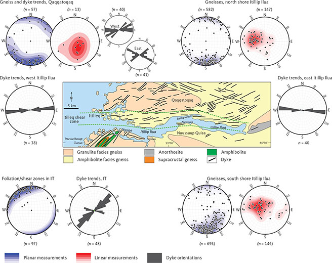
Fig. 16 Orientation plots for dykes and host gneisses in areas along and adjacent to Itillip Ilua. Data from the Inussuttusup Tunua (IT) area are from Jack (1978), the remainder are from this study. See Fig. 38 for contouring details. Planar measurements (blue shading) include all penetrative planar elements on outcrop scale in metadykes and host gneisses, typically a combination of mineral foliation and compositional layering (e.g. Fig. 22). Linear measurements (red shading) include all penetrative linear elements in metadykes and host gneisses such as mineral lineation, stretching lineation (typically quartz and feldspar aggregates), rodding, mullions and axes of minor folds (e.g. Fig. 23). Green dashed lines: denote the Itilleq shear zone.
In terms of metamorphic overprints, the dykes around Inussuttusup Tunua show the range from marginal samples displaying only minor overprints to samples from dyke centres, where the rock is totally recrystallised to a foliated garnet-amphibolite. With few exceptions, the original igneous texture is nevertheless still preserved or recognisable. In some dykes, garnet growth appears to have been initiated along irregular veins, then migrated into the rock and resulted in dendritic or ‘cauliflower’ textures. Primary orthopyroxene is found in a few of the dykes, whereas primary amphibole has not been positively identified but was posited by Hansen (1989) from the Nooralak peninsula just NE of Inussuttusup Tunua in outer Itillip Ilua (Fig. 2).
Jack (1978) described a sequence of metamorphic reactions, involving amphibole or biotite rims on ilmenite or clinopyroxene, or both, and a later stage of garnet growth that partially or completely replaced these rims. These observations correspond closely to those outlined in this study in Chapter 5. Jack (1978) attributes these corona-forming reactions to the mechanism of ‘autometamorphism’, which purports that metamorphic reactions progressed immediately after dyke emplacement driven by elevated temperatures and increased fluid content associated with later magma pulses. We propose an alternative interpretation of the initiation, progress and cause of these metamorphic reactions (see Section 3.1.6).
3.1.6 Itillip Ilua and surrounding areas
In inner Itillip Ilua and along the north shore of the outer fjord, dykes are broadly parallel with a predominant E–W-trending layering and foliation of the gneisses. Away from the fjord, dykes trend ENE to NE (Fig. 16). At first glance, it appears to be a simple case of dykes and their host rocks being overprinted by a dextral shear zone in which all structures and intrusions were rotated into parallelism by the stress-field responsible for the shear zone. Based on field observations, the structural history along and near Itillip Ilua is substantially more complicated. While it may be debatable whether the strong planar fabrics along Itillip Ilua conform to common definitions of a shear zone (e.g. Ramsay 1980), we nonetheless use the term ‘Itilleq shear zone’ here (Fig. 16).
Earlier workers observed that Kangâmiut dykes cut gneisses with a strong shear fabric in the Itillip Ilua area and described the dykes as having only minor structural and metamorphic overprints. Farther north, in Ikertooq, however, the dykes and their country rocks are strongly deformed and metamorphosed in amphibolite and granulite facies. In order to distinguish between these events, Watterson (1974) used the terms “Nagssugtoqidian 1” (Nag. 1) and “Nagssugtoqidian 2” (Nag. 2). Nag. 1 described the tectonic event responsible for the strong planar fabrics in the Itilleq shear zone and similar structures cut by dykes. Nag. 2 described a later high grade deformational and metamorphic event, which created the Ikertooq shear zone and similar structures throughout the Nagssugtoqidian orogen. Subsequent Rb–Sr whole-rock geochronology, however, indicated that Nag. 1 most likely was an Archaean event (and thus unrelated to Nagssugtoqidian deformation and metamorphism), which led Kalsbeek & Zeck (1978) and Kalsbeek (1979) to recommend abandoning the Nag. 1 and Nag. 2 terminology.
The strong planar fabric displayed in the Itilleq shear zone is truncated by tonalitic, dioritic, and granitic bodies in several places along Itillip Ilua (Figs 17A–C). A few of these undeformed rocks were dated by U–Pb of zircons to around 2.5 Ga (2492 ± 12 Ma by Kalsbeek & Nutman 1996, and 2498 ± 4 Ma by Connelly & Mengel 2000), confirming that the Itilleq shear zone is an Archaean feature. An identical Rb–Sr age (2500 Ma ± 40) was obtained by Hickman (1979) on an “aplite associated with a late-Nag. 1 pegmatite near Itilleq”.
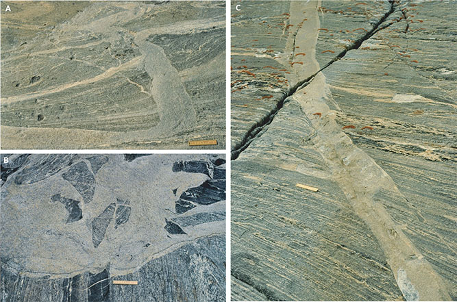
Fig. 17 Field examples of discordant tonalitic bodies from locations in and around Itillip Ilua. A: Vein of grey tonalite cutting across strong planar fabric in amphibolite facies host rocks. South shore, inner Itillip Ilua. Scale is 10 cm. B: Irregular, discordant body of grey tonalite with angular fragments of a strongly deformed and banded mafic and felsic host amphibolite facies gneiss. Brittle injections of delicate tonalite veins and off-shoots riddle the host gneiss in the lower left part of the panel (just left of ruler scale). South shore, inner Itillip Ilua. Scale is 10 cm. C: Grey tonalite vein, discordantly truncating the strong planar fabric of an amphibolite facies host gneiss. Apparent dextral offset along margin of intrusive vein can be seen in agmatite zone in centre of image. Delicate intrusion features show right-stepping geometry in a largely brittle domain. North shore, head of Itillip Ilua. Scale is 10 cm.
It is important to remember, that c. 450 My separate the older straight belt fabrics in the Itilleq shear zone from the events leading to the intrusion of Kangâmiut dykes and accompanying deformation. Also, 150 My separate that event from the earliest Nagssugtoqidian orogenic activities (see also Chapter 9).
From Inussuttusup Tunua and north, it appears that host rock structures and dyke orientations gradually bend clockwise, parallel to the predominant trend around Itillip Ilua (Fig. 16). In the following sections we describe the rocks and structures along Itillip Ilua, outside (Section 3.1.6.1) and inside (Section 3.1.6.2) the Itilleq shear zone.
3.1.6.1 Qaqqatoqaq and Nuussuup Qulaa
The country rocks at Qaqqatoqaq and Nuussuup Qulaa (Fig. 16) are believed to have suffered their last major phases of deformation and metamorphism in the Archaean (2740–2710 Ma, Kalsbeek & Nutman 1996). The gneisses on Qaqqatoqaq and Nuussuup Qulaa are intruded by the Kangâmiut dykes, which crosscut all structures and lithologies of the Archaean rocks. The bulk of the country rocks are quartzo-feldspathic gneisses of mainly tonalitic to granodioritic composition. The gneisses are heterogeneously layered rocks often transected by leucocratic veins forming an irregular network (Fig. 18A). Mafic inclusions of various shapes are distributed throughout the gneisses and occur as isolated lenses, pods and agmatite zones (Fig. 18B).

Fig. 18 Field examples of dykes from Saqqap Kangerluarsua. A: Veined grey gneiss on approaching a shear zone. Hammer is 45 cm. B: Grey gneiss veined by leucocratic material. Hammer in yellow dashed circle is 45 cm.
Rocks of obvious supracrustal affinity are rare at Qaqqatoqaq and generally do not constitute mappable units. Only one isolated occurrence of garnet-sillimanite-biotite gneiss was found in the central part of Qaqqatoqaq associated with a layered amphibolite.
At the head of Itillip Ilua, a large mass of anorthosite is present (Ellitsgaard-Rasmussen & Mouritzen 1954). The anorthosite is deformed and intruded by Kangâmiut dykes (Fig. 19A–C). In Fig. 19D, the anorthosite is cut by a gray tonalitic-dioritic sheet, which is remarkably similar to the c. 2.5 Ga tonalitic-dioritic bodies mentioned previously (Section 3.1.6; Fig. 17). While the tonalite-diorite sheet at this location has not been dated, its similar composition and appearance would support a pre-2.5 Ga age for the anorthosite.
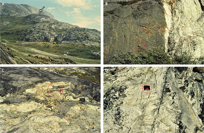
Fig. 19 Field examples of dykes and anorthosite from the head of Itillip Ilua. A: View towards east of the far western extent of the anorthosite body (Qaqortorsuaq mountain; Ellitsgaard-Rasmussen & Moritzen 1954). Amphibolite facies host gneisses in left foreground. In the centre of the photo, two 10–20 m wide, E–W-trending and discordant Kangâmiut dykes (two yellow arrows), can be traced up the hill, turning slightly to the right (south). Another, wider Kangâmiut dyke can be seen in the south-facing anorthosite wall in the far background (white arrow). B: Detail of sharp contact between Kangâmiut dyke (leftmost in A) and anorthosite. Note subtle (primary?) layering in dyke. Notebook (red dashed circle) is 11 x 18 cm. C: Irregular contact between Kangâmiut dyke and anorthosite host, suggesting only minor rheology contrast between dyke and host rock during emplacement or a subsequent structural overprint or both. Hammer (red dashed circle) is 45 cm long. D: Weakly foliated anorthosite intruded by grey, tonalitic sheet, similar to those shown in Fig. 17. Notebook (red dashed circle) is 11 x 18 cm.
The quartzo-feldspathic gneisses and their mafic inclusions show granulite facies assemblages in the western parts of Qaqqatoqaq and Nuussuup Qulaa, and amphibolite facies assemblages in the eastern parts (Fig. 16).
No large-scale structures have been mapped on Qaqqatoqaq and Nuussuup Qulaa, mainly due to an absence of appropriate marker horizons. Further west, in the Inussuttusup Tunua area, a major basin and a smaller dome structure, outlined by supracrustal rocks, were mapped by Davidson (1978) and Jack (1978; Section 3.1.5; Fig. 16).
The planar fabric in the quartzo-feldspathic gneisses is a combination of coarse compositional layering and a preferred habit orientation of mainly biotite (schistosity). On Qaqqatoqaq, the general structural trend, shown by the planar fabric, is moderately to steeply NE- or SW-dipping (Fig. 16), whereas on Nuussuup Qulaa, south of Itillip Ilua, the dominant strike is NE–SW. A gradual clockwise rotation of structures on approaching Itillip Ilua from the south is also evident (Fig. 16). In both areas, the challenging topography means that ground observations are limited.
Linear structures include: (1) minor fold axes; (2) lineation defined by elongate mineral aggregates (stretching lineation); (3) lineation defined by a preferred dimensional orientation of crystals with elongate habits (mineral lineation). Linear structures recorded in the Archaean gneisses are mainly of the first two types. Orientation diagrams of linear structures from Qaqqatoqaq (Fig. 16) show steeply SE-plunging lineation that are distinctly different from those along Itillip Ilua.
The broad map-view distribution and orientation of the dykes in these areas are shown in Fig. 16. Actual field mapping of dykes has taken place along the shore of Itillip Ilua and on a few N–S traverses across Qaqqatoqaq and south of the fjord. In the outer parts of Itillip Ilua, the dykes have been mapped in detail by Nash (1979a, b). All other dykes are traced from aerial photographs (see the simplified summary in Fig. 16).
All dykes are subvertical to steeply north-dipping. In the western part of Qaqqatoqaq, most dykes trend ENE, whereas in the eastern part, there are distinct NE- and NW-trending populations (Fig. 16). Within the Kangerlussuaq area, Escher et al. (1975) found that NNE-orientated dykes cut the roughly E–W-trending (85°–110°) dykes and a similar relationship was reported by Mengel et al. (1996). In Qaqqatoqaq, however, intersections between ENE- to NE-aligned dykes and the NW-trending dykes are more inconsistent, with NW-trending dykes both cutting (Fig. 20A) and being cut by ENE-aligned dykes (Fig. 20B), leaving open the possibility of a single prolonged period of intrusion of all dykes of different orientations, as noted by Escher et al. (1976a) from the Inussuttusup Tunua area.
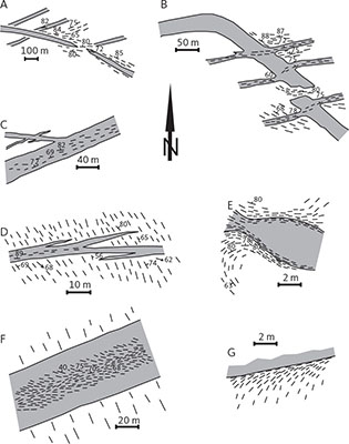
Fig. 20 Examples of dyke geometries and relationships between dykes of different orientations in the Qaqqatoqaq area (reproduced from Korstgård 1980). A: WNW-trending dykes cut NE-trending dykes. B: NW-trending dyke cuts across NE-trending dykes, but also turns into an NE-trending orientation. C: NE-trending dyke with WNW-trending apophyses. D: ENE-trending discordant dyke with apophyses showing right-stepping intrusion geometry. E: WNW-trending dyke shows dramatic thickness variations along strike. In thicker parts of dyke, its margin and the host gneiss show foliation development. In thinner parts of dyke, foliation is developed across the entire dyke. F: Sharply discordant ENE-trending dyke with internal foliation showing sinistral asymmetry. G: Structures in a host gneiss that rotates asymptotically into parallelism with margin of undeformed, discordant ENE-trending dyke.
The dykes are generally regular in form with a straight, parallel-sided appearance. On closer inspection, however, many dykes exhibit irregularities like offsets of dykes and apophyses (Fig. 20C). Variation in thickness along dykes over relatively short distances has been observed in only a few dykes in these areas (Fig. 20E). The dykes can be up to 60 m wide, with the mode being around 15 m. Dykes are dark brown to black, rather homogeneous, and without phenocrysts. Thicker dykes (>5 m) usually have finer-grained 1–20 cm wide margins, depending on the width of the dyke. Towards coarser-grained centres, larger dykes grade into doleritic and rarely gabbroic textures. Smaller dykes (<5 m) usually show a doleritic texture throughout except for a 2–3 cm wide fine-grained, often chilled, margin. The fine-grained margins usually have a porphyritic texture. In outcrops, where the geometry of foliations both inside and outside dyke margins can be established accurately, their interrelationship usually implies simple shear deformation of the dyke, with respect to its host. Such margin-parallel shear zones may occupy one or both sides of the dyke (Figs 20E, G), or in the case of wider dykes, even develop through its centre (Fig. 20F). There is a clear pattern of a sinistral shear component along NE dykes and dextral shear along NW dykes (Fig. 21), as described by Jack (1978) and Escher et al. (1976a) from the Inussuttusup Tunua area.
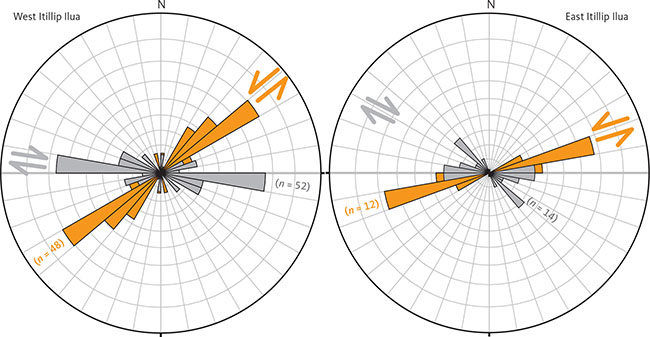
Fig. 21 Rose diagrams showing orientation of Kangâmiut dykes at Itillip Ilua. Sinistral (orange) and dextral (grey) shear along or in margins of dykes from western (left) and eastern (right) Itillip Ilua. In both cases, conjugate bimodal trends and shear distributions are roughly consistent with overall N–S compression. The obtuse bisectrix in western Itillip Ilua is orientated c. NNW, whereas in the east it is orientated N–NNE, suggesting a rotation of the stress field responsible for the observed distribution of shears. Note some overlaps between the two dyke sets in the acute bisectrix. Source: Korstgård & Park (unpublished data).
The preservation of subtle, brittle features along dyke margins may suggest that dykes preferentially intruded into pre-existing zones of weakness (fractures, foliations) in the host gneisses. Additionally, the fact that planar fabrics developed in and along the dykes could indicate a phase of localised deformation after the emplacement of the dykes.
3.1.6.2 Itilleq shear zone
Along the north and south shores of Itillip Ilua, the N-dipping compositional layering and schistosity of the gneisses is uniformly E–W-trending, as opposed to the oblique NE to SE trends across Qaqqatoqaq and the E to NE trends across Nuussuup Qulaa (Fig. 16). The c. 7 km wide zone along Itillip Ilua is made up of a number of E–W-trending panels of stronger deformation, which collectively constitute the Itilleq shear zone (Nash 1979a; Fig. 16). Individual panels of higher deformation are usually between a few metres and several tens of metres wide and alternate with less deformed areas (Fig. 22). They can not typically be traced for any significant distance along the strike. The apparent horizontal sense of shear inside these high deformation zones – based on regional patterns and on bends and drags along its boundaries – appears to have been dextral. The dominant direction of movement along these vertical to steeply N-dipping planes – as estimated from the stretching lineations on schistosity planes – plunges moderately to steeply to the W and WNW and is observed in both the gneissic host rocks and the dykes (Fig. 23A–C; summarised in the orientation plots of Fig. 16).
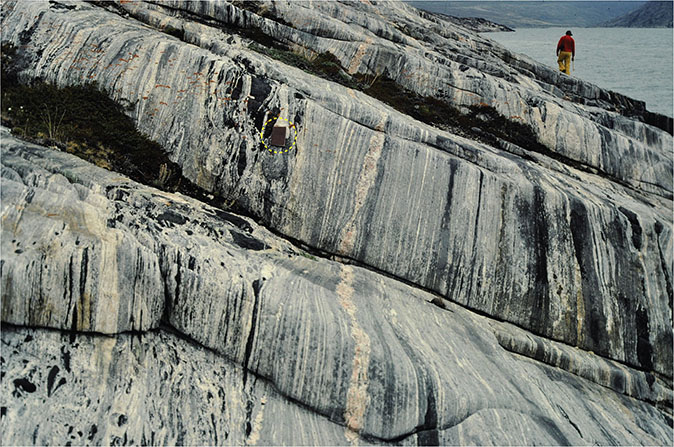
Fig. 22 Penetratively deformed tonalitic to granodioritic amphibolite facies Archaean gneiss. Disrupted mafic agmatite layers are visible beneath the notebook (yellow dashed circle). Late- to post-kinematic granitic veins alternating with panels of straight gneiss fabrics are also shown. Eqalugaarsuit, north shore of Itillip Ilua. Notebook is 11 x 18 cm.
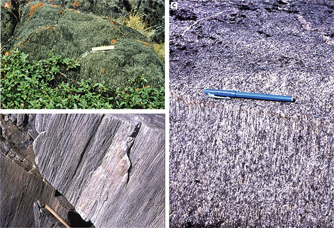
Fig. 23 Field examples of linear fabrics in dykes and gneisses. A: Steeply WNW-plunging lineation in the narrow part of a podded Kangâmiut dyke. The dyke width changes from 40 m in the widest part of the pod to less than 1 m in the thin part connecting the pods. Nuussuaq, south shore of Itillip Ilua. Scale is 10 cm. B: Steeply WNW-plunging linear aggregates of quartz and feldspar inside a strongly sheared grey amphibolite facies gneiss panel. Itilleq shear zone. Visible part of hammer is 30 cm. C: Steep lineation in quartzo-feldspathic gneiss. Qaqqatoqaq. Pen is 14 cm.
In apparent contradiction with those observations, there are a few spectacular sinistral delta-clasts on the horizontal surfaces on some of the high-strain gneiss panels (Fig. 24) with apparent rotation axes that parallel the previously described steeply west-plunging stretching lineation. Following Sanderson & Marchini (1984) and Robin & Cruden (1994), these observations are interpreted to reflect a local, but significant component of localised transpressive flow, perpendicular to the lineation. While these features are rare, they do support the presence of overall N–S transpressional shortening, similar to that described along dyke margins in Section 3.1.6.1.

Fig. 24 Field examples of sinistral shear from Eqalugaarsuit on the north shore of Itillip Ilua A: Sinistrally rotated, δ-type winged feldspar porphyroclast in high-strain gneiss panel viewed on a horizontal surface. Scale is 10 cm. B: Sinistrally rotated δ-type blocky feldspar porphyroclast in highly strained gneiss on horizontal surface. Upper part of photo shows discordant late-kinematic pegmatite. Scale is 10 cm.
In the high-strain panels, gneisses gain a very strong, almost mylonitic, planar fabric (Fig. 25A, B). Syn-kinematic leucocratic veins are transposed into parallelism with this planar fabric and often only survive as feldspar clasts (Fig. 24, 25B, 26A). Linear structures are equally well developed and are mostly composed of elongate quartz and feldspar aggregates (Fig. 23). Mafic layers (some of which could be dykes emplaced prior to shear-zone formation) likewise are converted to elongated lenses or agmatitic zones (Figs 22, 25C).
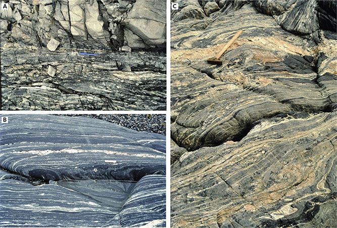
Fig. 25 Field examples of gneiss fabrics from Itillip Ilua A: Mylonitic zone in host gneiss adjacent to Kangâmiut dyke (upper part of photo). NW Nuussuaq, north shore of Itillip Ilua. Pen measures 13 cm. B: WNW-plunging stretching lineation in strongly sheared mafic gneisses, with several generations of discordant pegmatite veins. This outcrop represents one of the many high-strain panels in the Itilleq shear zone. Sinistral δ-clast seen in Fig. 24A is from this outcrop. Just NW of Eqalugaarsuit on the north shore of Itillip Ilua. Scale is 10 cm. C: Typical layered, polyphase, tonalitic to granodioritic amphibolite facies gneiss with mafic agmatites and several generations of pegmatites, some only mildly deformed (under hammer). This outcrop is typical of the basement gneisses outside the high-strain panels (e.g. Fig. 25B). Eqalugaarsuit. Hammer is 45 cm.
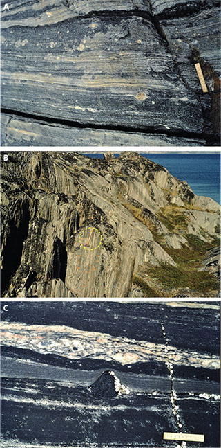
Fig. 26 Highly strained gneiss panels in the Itilleq shear zone. A: Detail of one high-strain panel in tonalitic-dioritic amphibolite facies gneiss, with widespread remnants of pegmatites, preserved as porphyroclasts (detail of rotated, winged porphyroclast in Fig. 24A). Just west of Eqalugaarsuit, north shore of Itillip Ilua. Scale is 10 cm. B: Straight, homogeneous amphibolite facies gneiss with steep stretching lineations. South shore of inner Itillip Ilua. Hammer in circle is 40 cm. C: Detail of high-strain panel in dark, tonalitic-dioritic gneiss with late-kinematic pegmatite showing subtle development of sinistral shear bands and an angular hornblendite fragment showing no rotation in this horizontal exposure. Just west of Eqalugaarsuit. Scale is 10 cm.
3.1.6.3 Dykes in the Itilleq shear zone
The pattern of distribution and orientation of the Kangâmiut dykes shows a marked change along Itillip Ilua where there is a concentration of dykes with an 80–90° orientation in the western part and a 90–100° orientation in the eastern part (Fig. 16). This slight change in the trend of the dykes coincides geographically with a similar change in the gneissic fabrics in the E–W-trending Itilleq shear zone (Fig. 16). Most dykes are vertical or dip steeply to the north. Many of the dykes in the Itilleq shear zone show little or no sign of deformation, and where NE- or NW-trending dykes occur with E–W dykes in the marginal zones of the Itilleq shear zone, they are not less deformed (as would be expected if they represented un-sheared relics) but are similar to their E–W counterparts. This regional deflection of the dykes can only be satisfactorily explained by a primary local change in the orientation of the stress field (i.e. dominant fabric in the host gneisses), which guided the intruding dykes. Such an observation was also noted in the Inussuttusup Tunua area (Jack 1978).
Due to the dominance of c. E–W-dyke orientations, very few intersections were observed inside or along the Itilleq shear zone. An exception is the dyke intersections visible on the north shore of Itillip Ilua just north of Equalugaarsuit where a large WNW- to NW-trending dyke cuts several smaller NE- to ENE-trending dykes (Figs 20A, 27) in the margin of the Itilleq shear zone as defined in Fig. 16. Both inside and outside the shear zone there are examples of dykes changing orientation (e.g. Fig. 20B) making any chronological distinctions between dyke sets – based on trends – doubtful. The simplest explanation is that the dykes were emplaced during a single protracted pulse. However, until these sets of dykes are dated, this remains speculative.
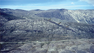
Fig. 27 Large WNW-trending dyke cuts several smaller ENE-trending dykes (Fig. 20A). Visible in the foreground is a road leading to the DYE-1 radar station (part of the Distant Early Warning line system of radar stations active from 1958 to 1988). Eqalugaarsuit, north shore of Itillip Ilua. Ridge with light coloured gneisses in foreground is c. 300 m high. White arrows indicate dyke intersections.
In contrast to the dykes on Qaqqatoqaq and Nuussuup Qulaa, the dykes hosted by the strongly deformed gneisses in the Itilleq shear zone can be highly irregular in thickness and intrusion geometry. Below, we present the two main dyke types: (1) podded dykes, which are exposed as pods and lenses, often separated or connected by very thin segments (Fig. 28), and (2) regular dykes with small, low angle apophyses and bayonets along their margins.
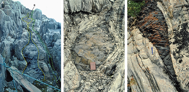
Fig. 28 Features in podded Kangâmiut dykes. A: Train of several pods (yellow outline) adjacent to un-podded thin dyke (green outline). North shore, mouth of Itillip Ilua. Pod in foreground (marked as B) is 1 m wide. B: Detail of pod shown in panel A. Note stronger deformation along dyke margins and in the adjacent host gneiss. North shore, mouth of Itillip Ilua. Notebook is 11 x 18 cm. C: Pod of Kangâmiut dyke showing discordance with gneissic layering (especially clear on left side near pen). Towards bottom of picture, dyke thins to a few centimetres before joining another, wider pod. South shore of Saqqap Kangerluarsua. Pen measures 13 cm.
We use the term ‘podded’ as a strictly non-genetic description of the dykes in question. While ‘pinch and swell’ would accurately describe the geometry, that term is typically restricted to phenomena of a tectonic origin (e.g. Fossen 2016, p. 316). As some features of the shapes and intrusion forms described in this Section are proposed to be of primary intrusive origin, we propose ‘podded’ as the best neutral term for the observations.
One of the best examples of a podded dyke is exposed across the Nuussuaq peninsula on the south shore of Itillip Ilua (Fig. 16). This dyke was mapped along an exposed length of c. 1.5 km and is characterised by relatively long pods connected by short, thin segments (Fig. 29). The shape of these pods in the horizontal section is elliptical and in the few cases where partial vertical sections were observed, these also appear elliptical. This 3D geometry is also suggested in horizontal sections by inclined dips of dyke contacts between country rock and dyke. Attempts to find outcrops that exposed the entire vertical geometry of a pod have been unsuccessful. It is therefore unknown if the pods are oblate or prolate spheroids or even triaxial ellipsoids. The podded dykes are mostly concordant, although some local discordances can be found (Fig. 28C).
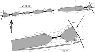
Fig. 29 Sketch of podded dyke across a small peninsula at Nuussuup Qulaa on the south shore of Itillip Ilua (location in Fig. 35). Note how the apophysis in the enlarged area is unaffected by the drastic changes in thickness, observed just a few metres away in the large dyke. “?” is not exposed. Reproduced from Korstgård (1980).
The shape of the podded dykes and their concordance with gneiss schistosity could suggest that the dykes were deformed into parallelism with gneiss structures and that their geometry is a boudinage, meaning a tectonic phenomenon. However, certain features of the dykes contradict this interpretation. The sketch in Fig. 30B shows part of a large, podded dyke from the north shore of Itillip Ilua. The dyke has a maximum width of about 50 m. Where the dyke narrows, intricate intrusive features are seen with small inter-connected apophyses forming an irregular network. The interconnecting apophyses are discordant to the gneiss schistosity and completely undeformed, hence the narrowing of the dyke cannot have been produced by deformation and must have been an original intrusive feature. Figure 30C shows a field example of the discordance between gneiss fabrics and the delicate dyke strands at the narrow tip of the pod.
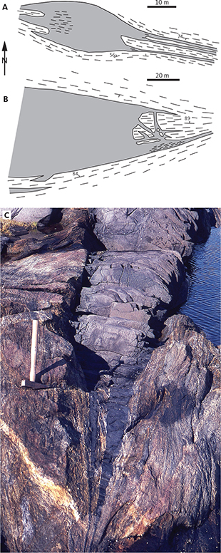
Fig. 30 Intrusive features in podded dykes from the north shore of Itillip Ilua. A: Field sketch of 20 m wide Kangâmiut dyke that over 20 m narrows to a couple of centimetre-wide strands. Reproduced from Korstgård (1980). B: Field sketch of 50 m wide Kangâmiut dyke pod at the end of which is an intricate network of interconnected apophyses that are discordant to the host rock foliation and entirely undeformed. This suggests that the thinning of the pod is a primary feature rather than the result of deformation. From Korstgård (1980). C: Delicate discordant features preserved along thin dyke strands at tip of pod in Kangâmiut dyke. Hammer is 40 cm.
Furthermore, although parts of the podded dykes are deformed at some localities, they generally do not appear more (or less) deformed than their straight-sided counterparts in the Itilleq shear zone and locally there are podded dykes within tens of centimetres of straight-sided, concordant dykes (e.g. right of the pod in Fig. 28A).
The E–W-orientation of the dykes in the Itilleq shear zone and the general concordance of dyke margins and gneiss fabrics are therefore most likely primary features. The strong fabric in the gneisses constitutes a closed planar discontinuity. A major effect of such a discontinuity is to lower the tensile strength and shear strength along the discontinuity surface. The schistosity planes in the Itilleq shear zone will therefore be preferred sites of the fracture arrays forming ahead of dyke magma emplacement, and the geometry of the fractures will be controlled by the stress affecting the rocks. As magmatic pressure increases, the fractures will dilate into one of several final dyke forms observed along Itillip Ilua.
Nash (1979b) suggested that the podded form of many of the dykes in western of Itillip Ilua in 3D resembles that of an upward-pointing hand with the narrow parts connecting individual fingers (fig. 3 in Nash 1979b). Observations of podded dykes in the eastern part of Itillip Ilua, however, suggest that the 3D shape may be more like an egg carton, displaying variations of pod geometry in both horizontal and vertical directions (Fig. 31).
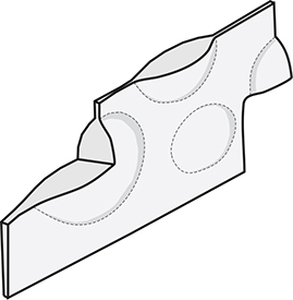
Fig. 31 Interpretive sketch of the 3D geometry of podded dykes. Based on field observations of mostly horizontal and a few vertical outcrops, as well as structural readings along pod margins. Pods can vary in thickness from 1 m to 60 m. Reproduced from Korstgård (1980).
The distribution and orientation of dykes around Itillip Ilua (including Qaqqatoqaq, Nuussuup Qulaa and the Itilleq shear zone) seem unrelated to the amount of deformation in the dykes solely based on visual observations. Dykes in this area are deformed internally and generally not together with their country rocks. The extent of deformation in the dykes shows considerable variation, which does not, however, correlate with their position either outside or inside the Itilleq shear zone.
In the field, dyke deformation is expressed as a schistosity defined by a parallelism of flattened feldspar aggregates and amphibole aggregates. In coarser-grained dykes, an alignment of amphiboles is visible (Figs 23A, C). A lineation formed by elongate aggregates of amphibole and feldspar accompanies the schistosity in many dykes and often becomes the dominant structural element, especially in the thin zones connecting the pods (Figs 23A, 32).
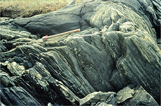
Fig. 32 Strongly deformed tonalitic-granodioritic host gneiss adjacent to narrow part of podded dyke (upper part of figure). The dyke does not exhibit the same structures as seen in the host rocks. Stretching lineation (seen as mineral aggregates in right side of image) plunge to WNW. South shore, head of Itillip Ilua. Hammer is 40 cm.
Similar to dykes outside the Itilleq shear zone, dykes inside the zone can show shear on one or both margins of the dyke and even through their centres. In more intensely deformed dykes, and very often in the narrow parts connecting the pods, the shearing affects the entire dyke width, and the schistosity becomes concordant or near concordant with the margins of the dyke (Fig. 33). The sub-vertical to steeply W- and WNW-plunging aggregate lineation in dyke margins and in thin zones between pods are interpreted to have formed during overall N–S compression with a considerable vertical component.
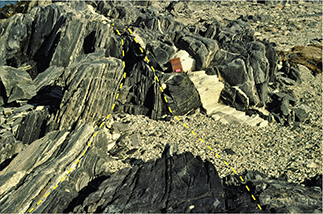
Fig. 33 View from the widest part of the pod towards the narrow part (outlined in yellow dashed lines) on the south shore of inner Itillip Ilua. Towards the narrow part, both dyke and host gneisses are increasingly strongly deformed, especially along the dyke’s left margin. Late, discordant leucocratic pegmatite truncates the narrow zone. Notebook is 11 x 18 cm.
Another population of dykes display clear discordance with the sheared gneisses and preserve delicate boundary features such as thin, low angle apophyses, bayonets, and bridges (examples in Fig. 34). While these dykes clearly intruded relatively brittle host rocks long after the formation of its penetrative regional fabric, an apparent and consistent asymmetry of the delicate intrusion features carries information about the geometry of the stress field encountered by the dykes. The dykes can conveniently be split into two categories based on the asymmetry of apophyses along their sidewalls, into either ‘left-stepping’ or ‘right-stepping’ intrusions (see Fig. 34). Our observations, both outside and inside the Itilleq shear zone, indicate that dykes that trend north of east (‘counter-clockwise’ relative to the dominant gneissic fabric) are typically left-stepping, whereas dykes that trend clockwise relative to the gneissic fabric are right-stepping. The stress system responsible for these features is consistent with an approximately N–S-directed maximum horizontal stress. There are possibly minor fluctuations towards NNW–SSE in west Itillip Ilua and towards NNE–SSW in the eastern part, based on the subtle variations in the orientations of both the hosting straight belts and dykes from west to east. In westernmost Itillip Ilua, Nash (1979a) also reports detailed evidence for greatest compressive stress (σ1) being orientated approximately N–S during stage-2 shears accompanying or slightly post-dating dyke emplacement.
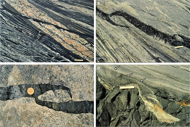
Fig. 34 Intrusion features in Kangâmiut dykes in Itilleq shear zone. A: Strongly sheared, straight gneiss truncated by late-kinematic granitic pegmatite (clockwise relative to gneissic fabric) in turn cut by undeformed thin Kangâmiut dyke (counter-clockwise). Eqalugaarsuit, north shore of Itillip Ilua. Scale is 10 cm. B: NE- to ENE-trending Kangâmiut dyke cutting host gneisses in a counter-clockwise orientation relative to gneiss layering and showing overall left-stepping intrusion geometry. Preservation of delicate apophyses suggest no post-emplacement deformation. Eastern Nuussuaq, south shore Itillip Ilua. Scale is 10 cm. C: 5 cm wide NNE-trending Kangâmiut dyke cutting heterogeneous granitoid with supracrustal xenoliths (not seen in picture) and showing right-stepping intrusion asymmetry. This outcrop is south of the Itilleq shear zone. South shore, mouth of Itillip Ilua. Coin diameter is 21 mm. D: Margin of a discordant, left-stepping Kangâmiut dyke (main body to lower left in picture) with a delicately preserved thin apophysis that cuts the straight planar fabric in its host gneiss (from middle of photo towards top left, shown by arrows). Eqalugaarsuit, north shore Itillip Ilua. Scale is 10 cm.
While the two types of dykes described above are quite different in appearance, they clearly occupy the same temporal window (i.e. pre-Nagssugtoqidian orogeny and post-straight belt structures in the Itilleq shear zone). There are at present no conclusive chronological data to identify their relative ages. If they are broadly the same age, as we suspect, the differences in geometry are indicative of variations in host gneiss properties and the ambient stress field at the time of intrusion. The dykes truncating the straight fabrics in the Itilleq shear zone intruded brittle rocks and clearly escaped subsequent deformation as shown by the preservation of subtle intrusion features. In contrast, the podded dykes and the dykes outside the Itilleq shear zone, while still being discordant and displaying a plethora of primary intrusive features, did subsequently deform along their margins, presumably related to Nagssugtoqidian deformation. Further analysis is needed to refine this sequence of events.
3.2 Dykes and country rocks of the Ikertooq region (from Saqqap Kangerluarsua to Maligiaq)
3.2.1 Saqqap Kangerluarsua (Kangerluarsuk)
The quartzo-feldspathic rocks along the southern shore of Saqqap Kangerluarsua (Kangerluarsuk) are part of the Archaean gneisses of Qaqqatoqaq and Nuussuup Qulaa. In the western part of the south shore of Saqqap Kangerluarsua (Fig. 35), rocks are in granulite facies, and to the east these are in amphibolite facies. The Kangâmiut dykes crosscut structures and lithologies of the quartzo-feldspathic gneisses inside both granulite and amphibolite facies areas. At several localities along the southern shore of Saqqap Kangerluarsua, weak NW–SE-trending Archaean structures (Fig. 16) are transected by E–W-trending, subvertical zones of ductile deformation, akin to the pre-dyke deformation zones at Itillip Ilua. These zones are often also loci of intrusion of the Kangâmiut dykes.
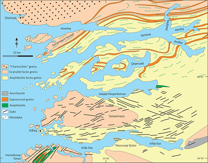
Fig. 35 Simplified geological map of the Itillip Ilua – Ikertooq region. The Ikertooq shear zone is located along the central supracrustal bands in Maligiaq and roughly follows Itillip Ilua. After Grocott (1977), Allaart & Jensen (1979), Jack (1978) and Korstgård (1980).
Pre-dyke deformation zones can be found at several localities across Qaqqatoqaq but are particularly well exposed along the southern shore of Saqqap Kangerluarsua and characterised, as in the Itilleq shear zone, by ductile deformation along E–W-trending and subvertical shear planes. The shear zones along the southern shore of Saqqap Kangerluarsua are discrete and well-spaced but are much more numerous than at Qaqqatoqaq. Farther north into Saqqap Kangerluarsua, such steep deformation zones become still more numerous and eventually pervade the gneisses completely. Along the northern shore of Saqqap Kangerluarsua, these are partially overprinted by subsequent Nagssugtoqidian deformation and become more difficult to recognise. In stark contrast to the south shore, the planar and steep fabric of both stronger deformations and dykes become deformed and inter-folded along the north shore of Saqqap Kangerluarsua and in Qeqertalik, inside and during what is considered to be the Nagssugtoqidian deformation proper (Figs 36A, C, 37B).
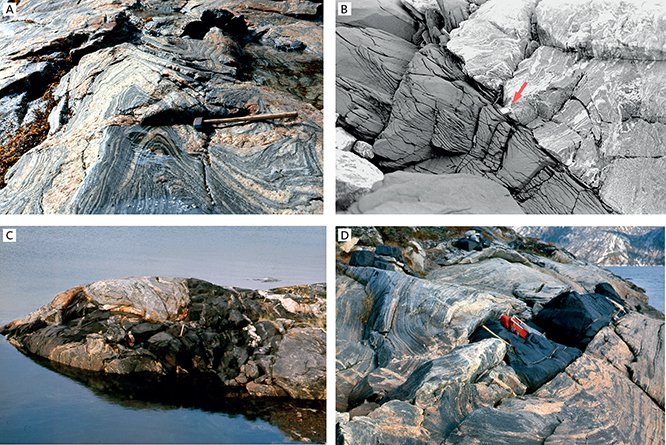
Fig. 36 Field examples of gneisses from the eastern south shore of Saqqap Kangerluarsua. A: Folded quartzo-feldspathic gneisses. B: Metadyke cross-cutting quartzo-feldspathic gneisses. Compass (by red arrow) is 12 cm. C: Folded metadyke in gneisses. D: Fold in gneisses wrapping around metadyke. Hammer is 40 cm.
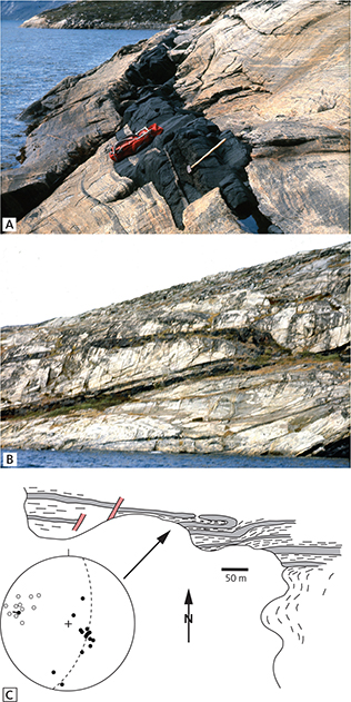
Fig. 37 Field examples of dykes from the north shore of inner Saqqap Kangerluarsua A: Mostly conformable relationships between gneissic banding and metadyke orientation. Hammer is 40 cm. B: Tightly folded metadyke with shallow north-dipping axial plane and an axis that plunges shallowly towards the west. Height of section c. 200 m. C: Sketch map, including locality B. Discordant pegmatites are shown in red. Filled circles in the stereogram represent poles to measured foliation. Open circles plot measured lineation.
While Kangâmiut dykes in Itillip Ilua, Qaqqatoqaq and Nuussuup Qulaa and along the southern shore of Saqqap Kangerluarsua may be sheared either along their margins or internally, these dykes are never folded. This situation changes radically at the head of and along the northern shore of Saqqap Kangerluarsua. From here and northwards, dykes are always thoroughly deformed, metamorphosed and folded together with their country gneisses. This transition may be illustrated by a series of field examples, where Fig. 36B shows an example of relatively weak Nagssugtoqidian deformation, superimposed upon gneisses with apparently Archaean structures. The dyke, though thoroughly deformed and metamorphosed, cross-cuts the gneiss structures and shows very little, if any, effects of Nagssugtoqidian folding. Figure 36C, from a small peninsula at the head of Saqqap Kangerluarsua, shows an example of Nagssugtoqidian folding of both the dyke and its country gneisses. The gneisses are moderately affected by Nagssugtoqidian deformation, and local discordances between dyke and gneiss are preserved. In other places with even stronger Nagssugtoqidian overprints, dykes and gneisses become conformable and folded together (Fig. 36D). Along the northern shore of Saqqap Kangerluarsua, dykes and gneiss structures are mostly conformable (Fig. 37A) and often folded. Major folds are near isoclinal (Figs 37B, C) with shallow, west-plunging axes.
The general orientation of planar and linear structures in Saqqap Kangerluarsua is significantly different, however, from what was observed at Qaqqatoqaq (Fig. 16). Planar structures are now striking between NNE and E, while linear structures dip shallowly to moderately to the WNW (Fig. 38).
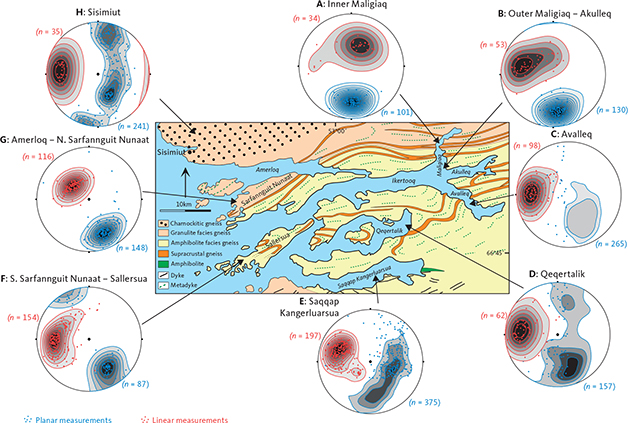
Fig. 38 Geological map (location in Fig. 2), with stereographic plots that show the poles of planar (blue) and linear (red) measurements in the Saqqap Kangerluarsua – Ikertooq region. These points are further contoured, using Stereonet v 11 software (https://www.rickallmendinger.net/stereonet) with Kamb contouring, interval 2σ. A–E: data from Korstgård (1980). G–F: data from Grocott (1977). H: data from Davidson (1978). Planar and linear structures defined in Fig. 16.
3.2.2 Qeqertalik and Avalleq
The area from Qeqertalik to Avalleq (Fig. 35) is characterised by large-scale folded country rock fabrics and metadykes that are metamorphosed in low amphibolite facies (see Section 6.2). The country rocks now also include significantly more layers of supracrustal rocks, mainly garnet-biotite gneisses, mica schists and amphibolites (Figs 35, 39A–D). The mineral parageneses in the quartzo-feldspathic gneisses are quartz, alkali-feldspar, plagioclase, green biotite, epidote and subordinate muscovite and blue-green amphibole. Mica schists and garnet-biotite gneisses of the supracrustal units have garnet and graphite in addition to the above-mentioned minerals, but not muscovite, epidote or amphibole.
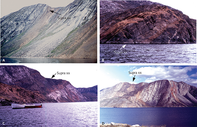
Fig. 39 Field examples of supracrustal sequences (Supra xx). A: Steeply NW-dipping supracrustal sequence in the south-easternmost part of Qeqertalik. Height of cliff c. 150 m. B: Moderately NW-dipping supracrustal sequence along east shore of Avalleq. Height of cliff in foreground c. 20 m. C: Shallowly NW-dipping supracrustal sequence along east shore of Avalleq. D: Steeply NW-dipping supracrustal sequence in Avalleq. Height of cliff c. 250 m.
The dykes consist mostly of plagioclase and amphibole with minor amounts of titanite and quartz and are thoroughly deformed and metamorphosed. Garnet is rare in the metadykes but may occur in amphibolites associated with supracrustal gneisses. In the quartzo-feldspathic gneisses, it is difficult to determine whether parageneses are a result of pre- or post-dyke metamorphism since the country rocks in Itillip Ilua and Saqqap Kangerluarsua – that were affected by only pre-dyke metamorphism – show the same parageneses. Only in a few cases, where epidote or biotite crystallised to form part of a post-dyke structure (e.g. axial plane schistosity or mullion), can the relative age of the mineral assemblage be established. However, considering the thoroughness of the metamorphism of the Kangâmiut dykes and the pervasive change in structure of the gneisses, it seems most likely that the country rocks also recrystallised after the dykes, during regional Nagssugtoqidian deformation and metamorphism.
The gneisses show strong linear and planar fabrics. The planar fabric is usually a combination of a fine compositional layering and a biotite schistosity (Fig. 40A–C). The general trend of the planar fabric is NNE–SSW in Qeqertalik (Fig. 38), with a moderate dip to the NNW, i.e. only a slight change from the orientations in Saqqap Kangerluarsua (Fig. 38). The linear structures are mainly stretching lineations, defined by aggregates of quartz and feldspar and minor fold axes and to a lesser extent mineral lineation defined by preferred habit orientation of elongate minerals.
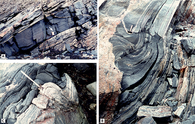
Fig. 40 Field examples of banded gneiss from inner Qeqertalik. A: Conformable metadyke in banded gneiss. Notebook at arrow is 18 cm long. B: Banded gneiss that is both folded and cut by a discordant pegmatite. Hammer is 40 cm long. C: Conformably folded metadyke and gneiss banding. Hammer is 40 cm long.
The folds in the area affect the compositional layering and schistosity of gneisses (Fig. 41A) as well as dykes (Fig. 41B). Major folds tend to be tight, with axial planes dipping steeply to the north and axes plunging gently to the west. These structures are clearly outlined by contrasting metadykes (Fig. 41B), by supracrustal bands and by planar fabrics in the quartzo-feldspathic gneisses.
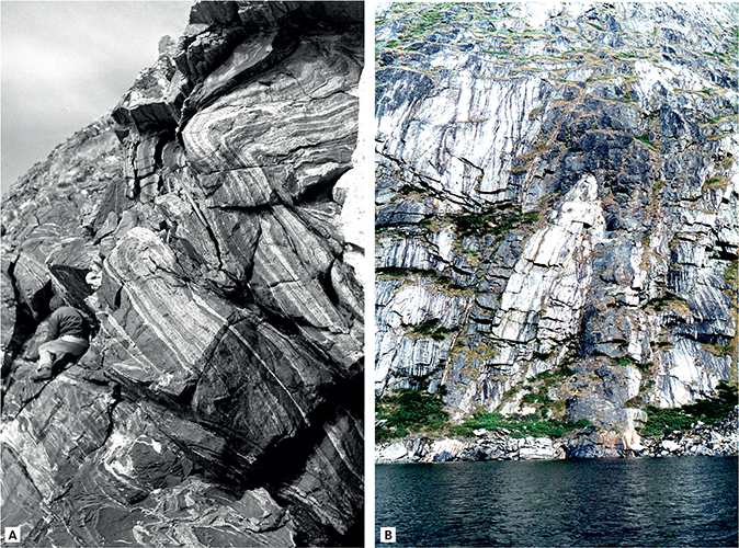
Fig. 41 Field examples from innermost Qeqertalik. A: NW-verging folded banded gneisses looking west. Person for scale. B: Folded metadyke looking east. Height of section c. 50 m.
The Kangâmiut dykes in Qeqertalik and Avalleq were thoroughly metamorphosed and deformed during Nagssugtoqidian orogeny. No trace of their original igneous microstructure is preserved. However, original discordances are often observed and the metadykes are still clearly recognisable as originally intrusive bodies (Fig. 42A, B). Planar structures in the dykes are mainly a schistosity defined by the preferred orientations of elongated amphiboles. Occasionally, a compositional layering on a centimetre scale is developed, which appears to have started as a segregation of plagioclase inside the metadykes. Linear structures are also defined by the preferred orientations of elongated amphiboles or appear as stretching lineation defined by aggregates of plagioclases (Fig. 42C).
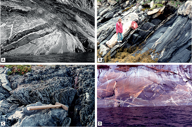
Fig. 42 Field examples from north-east shore of Avalleq. A: Banded gneiss with older mafic bodies conformably cut by c. 1 m wide Kangâmiut metadykes. B: Conformable metadyke in gneiss. C: Stretching lineation in metadyke defined by plagioclase aggregates. Hammer is 40 cm. D: Disrupted metadyke in gneiss. Large pod is c. 10 m long.
In addition to the major folds, described here, thin metadykes often display smaller scale folds (Fig. 40C), but no axial planar schistosity was found associated with these folds. Boudinaged (disrupted) metadykes were found in the northern part of Avalleq (Fig. 42D). There is considerably less variation in the general orientation of planar and linear structures in Qeqertalik and Avalleq (Fig. 38) compared to those in Saqqap Kangerluarsua.
3.2.3 Akulleq and Maligiaq
The area between Akulleq and Maligiaq is characterised by strong deformation of both dykes and their country rocks, as well as an increase in metamorphic grade from amphibolite to granulite facies.
Metamorphic mineral assemblages in the rocks change radically along outer Avalleq–Akulleq. In the quartzo-feldspathic gneisses epidote and muscovite disappear and give rise to assemblages characterised by biotite and amphibole, in addition to feldspar and quartz. Further north, in Maligiaq, metamorphic clinopyroxene and orthopyroxene appear simultaneously with a decrease or near disappearance of alkali-feldspar in the quartzo-feldspathic gneisses.
In the metadykes between the southern shore of Akulleq and midway into Maligiaq, clinopyroxene, and to a lesser extent garnet, become important members of the mineral assemblage (Fig. 35). Farther north, in the inner parts of Maligiaq, orthopyroxene appears.
Continuing across Akulleq, from Avalleq, and especially towards the outer parts of Maligiaq, there is an increase in both the intensity and parallelism of the planar fabrics of gneisses (Fig. 38). The intensity of this planar fabric culminates in the central part of Maligiaq (Fig. 38), where the planar fabric strikes E–W and dips around 60° towards the north (Fig. 43A). The planar fabric here developed as a combination of a fine compositional layering and a biotite schistosity (Fig. 43C).
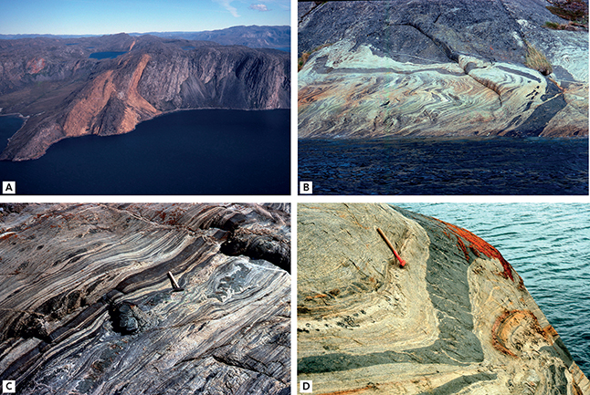
Fig. 43 Field examples from around Maligiaq. A: Steeply north-dipping and orange weathering supracrustal sequences, where gneisses to the right in the picture contain conformable metadykes. Height of main cliff about 400 m. Near mouth of Maligiaq. B & C: Banded gneisses and metadykes folded inside a low deformation zone in inner Maligiaq. Dyke at water’s edge in B is approximately 1.5 m wide. D: Thin metadyke conformably folded in a high deformation zone in Maligiaq. Hammer is 40 cm.
Along Ikertooq and in the outer parts of Maligiaq, linear structures (stretching lineation and mineral lineation) plunge shallowly to the west. About midway into Maligiaq, however, there is a sudden change in the direction of the linear structures from shallowly west to steeply north-plunging. This change in direction coincides with the beginning of an intensification of planar fabrics. The change in direction of the linear structures also approximately coincides with the onset of granulite facies metamorphism. However, from field observations it is clear that the beginning of granulite facies is well within the zone of strong deformation, about midway into Maligiaq.
On a map scale (Fig. 35), the planar structures along Akulleq and in Maligiaq define a linear zone that runs approximately east to west. This linear zone can be followed towards the west on Sarfannguit Nunaat (Sarfannguaqland; Grocott 1977) and eastwards on aerial photographs for at least an additional 50 km. The linear nature of the zone is emphasised by supracrustal bands (Fig. 43A).
The intensity of deformation decreases in the northern part of Maligiaq, where E–W panels of low strain (Fig. 43B) alternate with zones of strong deformation (Fig. 43C). Further north into Maligiaq, Nagssugtoqidian deformation appears to be quite low, as judged by a decreased intensity of fabrics and tightness of folds in dykes and gneisses. Dykes and compositional layering of gneisses (Fig. 43D) are only gently folded, in contrast to the tight folds and strong schistosity characterising the gneisses in the higher strain areas.
Based on the evidence summarised here and from previous contributions (Noe-Nygaard & Ramberg 1961b; Watterson 1974; Grocott 1977, 1979; Korstgård 1979a, b), the Nagssugtoqidian deformation along and north of Ikertooq is interpreted as a zone of strong deformation, characterised by ductile overthrusting towards the SSE along a moderately dipping thrust plane. The estimated width of the overthrusting zone in Maligiaq is about 5 km and its southern boundary is located about 2.5 km north of the Maligiaq mouth. The amphibolite-granulite facies boundary is located about 4 km north of the mouth and appears to parallel the thrust zone in the horizontal as well as in the vertical plane.
The metadykes in Maligiaq occur in three different metamorphic-structural settings relative to the thrust zone defined here:
- Along the north shore of Ikertooq, metadykes are mostly conformable to gneiss structures and lithological boundaries (Fig. 44A), but locally, discordant relationships to the country rocks are preserved (Fig. 44B). The metadykes have a strong planar fabric, defined mainly by preferred orientation of elongated amphibole aggregates, and commonly a well-developed stretching lineation that plunges shallowly to the WNW (Fig. 38). Mostly tight to isoclinally folded metadykes are common (Fig. 44C), with fold axes that are parallel to the lineation.
- Within the zone of strong Nagssugtoqidian deformation (i.e. the thrust zone, immediately north of Maligiaq), all dykes are parallel to the planar structures in the gneisses and mostly straight and parallel-sided (Fig. 44A). However, towards the south, within the amphibolite-facies part of the thrust zone, dykes may be broken up or boudinaged (Fig. 44D).
- North of the thrust zone, where all rocks are in granulite facies, the metadykes are often more irregular, yet may cross-out gneiss structures (Fig. 45A) and may also be folded together with the gneisses (Fig. 45B).
4 Igneous mineralogy and geochemistry of the Kangâmiut dykes
For this study, we have compiled a suite of published and unpublished geochemical data of Kangâmiut dykes from Maniitsoq to Ikertooq (Fig. 46; Appendix 1). The published studies describe the chemistry of the dykes and proposed models for their petrogenesis. However, our focus here is on identifying any regional compositional variations from Maniitsoq to Ikertooq and the control these could have on the post-emplacement metamorphic overprints on the dykes, if any. We consider such an analysis important and necessary as it will allow distinction to be made between mineral compositional variations resulting from varying metamorphic conditions versus those reflecting bulk rock compositional effects. Rather than view these data altogether or by source, we view them geographically in 11 areas (Areas 01 to 11 in Fig. 46) from south to north. These areas are defined according to sample density, host rock character, structural variations and metamorphic grades of host rocks (and dykes).
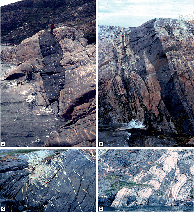
Fig. 44 Dyke-gneiss relationships in northern Ikertooq. A: Steeply N-dipping metadyke is broadly conformable with gneiss banding. Minor discordances, however, are preserved in the foreground. B: Tightly folded and steeply N-dipping dyke with rare discordant relationships with its host gneiss. Hammer is 40 cm. C: Subhorizontal hinge zone of synformally folded metadyke, enhanced by felsic veins. Hammer is 40 cm. A, B and C photos from north shore of Ikertooq close to mouth of Maligiaq, looking west. D: Disrupted metadykes in a 50 m wide, steeply N-dipping high-strain zone in amphibolite facies gneisses. East shore, mouth of Maligiaq.
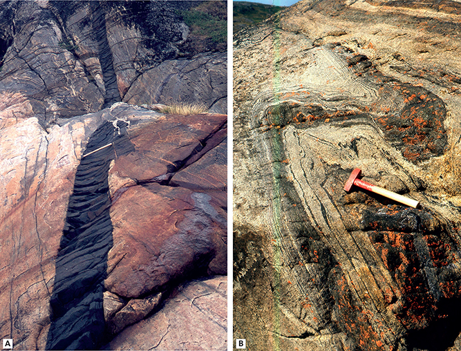
Fig. 45 Field examples from inner Maligiaq. A: Discordant and little deformed metadyke. Hammer is 40 cm. B: Metadyke that is conformably Z-folded in granulite facies gneisses. Hammer is 40 cm.
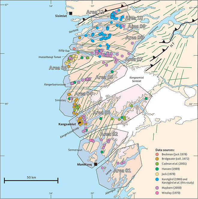
Fig. 46 Simplified geological map of the study area, showing the distribution and sources of analysed samples and the subdivision into areas based on sample density, host rock character, structural variations and metamorphic overprints observed in the dykes. NF: Nagssugtoqidian Front (see also Fig. 3). Data sources (see Supplementary File S1 and Appendix 1 for details): Beckmann (Jack 1978); Bridgwater (coll. 1972); Cadman et al. (2001); Hansen (1989); Jack (1978); Korstgård (1980); Mayborn (2000); Windley (1970).
In using basic dykes as monitors of post-emplacement metamorphism, the exact age of the dykes is not critical. If the basic dykes are of similar composition and were not metamorphosed prior to Nagssugtoqidian orogeny, they are all ideally suited for the purpose outlined here, and in Chapters 1 and 2.
4.1 Igneous mineralogy
Dykes with preserved igneous mineralogy, or with only very minor secondary mineral growth, can be found along almost the entire area from Maniitsoq to Itillip Ilua. As we discuss in Chapter 5, the degree of metamorphic overprinting on the dykes is extremely varied, both within an outcrop and across the study area, and preserved primary igneous mineralogy and texture can be found throughout.
The typical primary mineral phases are plagioclase, clinopyroxene, Fe-oxides and accessory minerals such as apatite, zircon and quartz. Olivine was not found. Primary amphibole or orthopyroxene or both are less common but do occur across the area. In the Inussuttusup Tunua area, Jack (1978) describes how the dominant pyroxene in the E–W dykes is pigeonite, which is commonly inverted to orthopyroxene and typically intergrown with clinopyroxene. The older, black feldspar dykes (also E–W-trending) are characterised by having primary orthopyroxene (not converted from pigeonite) as the only pyroxene.
The description here focuses on the main Kangâmiut dyke swarm, with its broad distribution and apparent homogeneity, while other dyke sets will be mentioned when relevant.
Considering the large areal extent of the swarm, the dykes are fairly homogeneous. Grain sizes vary from 0.1–0.5 mm in dyke margins to 1–3 mm in centres. Dyke margins generally exhibit ophitic to sub-ophitic textures (Fig. 47), often with large phenocrysts of plagioclase, clinopyroxene and locally what appears to be amphibole, set in a fine-grained, chilled matrix.
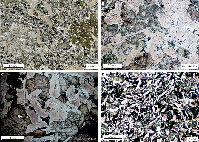
Fig. 47 Photomicrographs from Kangâmiut dykes with no or only minor metamorphic overprints. A: Chill of 30 m wide NNE-trending dyke. Primary clinopyroxene (left) and amphibole (right, brown-green) overgrowing a finer-grained matrix of plagioclase, clinopyroxene and ilmenite. Large primary plagioclase in upper part of picture. Sample 430267. South shore, mouth of Kangerlussuatsiaq. B: Sample 4 m from contact of 40 m NNE-trending dyke. Coarse-grained clinopyroxenes and subhedral plagioclases, with minor replacement of clinopyroxene by pale-green amphibole. Sample BH L-186197b. 10 km NNE of Maniitsoq, collected by Hansen (1989). C: Fresh, coarse-grained clinopyroxene–orthopyroxene–plagioclase assemblage from the centre of E–W dyke. Compositional zoning in plagioclases enhanced by variable ‘dusting’ by fine-grained particles. Sample JK 1332, south shore, outer Itillip Ilua. D: Fine-grained matrix of elongate plagioclase laths and interstitial clinopyroxenes. Incipient formation of pale-green amphiboles on margins of ilmenite and clinopyroxene. Sample JK 1328, south shore inner Itillip Ilua. Mineral abbreviations follow Whitney & Evans (2010). Amp: amphibole. Cpx: clinopyroxene. Pl: plagioclase. Opx: orthopyroxene.
Plagioclase laths have length:width ratios of 10:1 to 20:1, and are randomly orientated, except near the dyke wall (Jack 1978) where they may show alignment parallel with the contact. Plagioclase composition varies from An60 to An65 (i.e. labradorite) in the core of phenocrysts to An40 (i.e. andesine) in the rim. Orthoclase content is typically <2%. Individual crystals of plagioclase are often clouded with reddish to brownish very fine-grained particles (Figs 47B, C). These areas tend to clear up during incipient metamorphic overprints so the cloudiness may be a pre-metamorphic feature.
Compositionally, the clinopyroxenes fall in the augite and diopside fields in the pyroxene quadrilateral (Fig. 48C). The cluster straddling the diopside-augite boundary represents analyses from clinopyroxenes in Areas 08-11, including clearly metamorphic minerals from Areas 10 and 11. The spread in the augite-field is dominantly from the southern areas, where igneous pyroxenes show variable post-emplacement effects, including incipient hydration (Fig. 48C).
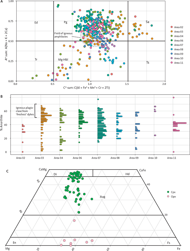
Fig. 48 Compositions of igneous and metamorphic minerals in Kangâmiut dykes (analyses not available from dykes in Areas 01 and 05). A: Compositions of all amphiboles analysed for this study. Axes as defined in classification scheme of Hawthorne et al. (2012). Field of interpreted late-stage magmatic amphiboles (e.g. amphibole in Fig. 47A) is grey and outlined by a dashed black line. Amphibole end-member abbreviations: Ed: Edenite; Pg: Pargasite; Sa: Sadanagaite, Tr: Tremolite, Mg-Hbl: Magnesio-hornblende, Ts: Tschermakite. B: Compositions of all plagioclases analysed for this study. Each dot represents an analysis. Binsize along the y-axis is 2% An. Fresh, unaltered plagioclases fall in the An50–An65 range. Metamorphic plagioclases, initially in rims adjacent to amphiboles or garnets or both, show lower An contents (<An30) in Areas 02–06. With higher metamorphic grades (Areas 08–11), An increases and converge around An40–An50 (cf. Fig. 82). C: Compositions of selected pyroxenes analysed for this study. Igneous clinopyroxenes (including those that have experienced initial replacement by amphibole) occupy the Aug field, whereas metamorphic clinopyroxenes (Areas 10–11) straddle the Di–Aug field. Orthopyroxenes (range from En70 to En40 with clearly metamorphic orthopyroxenes showing a narrow range of En60–50. Cpx: clinopyroxene. Opx: orthopyroxene. Pyroxene end-member abbreviations: Di: Diopside, Hd: Hedenbergite, Aug: Augite, En: Enstatite, Fs: Ferrosilite.
Orthopyroxenes have been observed and analysed in 15 samples. They show a range in compositions from En40 to En70 (Fig. 48C), with the clearly metamorphic orthopyroxenes from the northernmost areas in the narrower range of En50–En60. Orthopyroxenes do not show a preference for either the N–NE-trending dykes or the (rarer) E–W-trending dykes.
Primary amphibole is not common and potential candidates were only found in one sample from the southern part of the study area but has been reported in several previous studies. The sample in question has experienced no or only minor hydration of primary clinopyroxenes, and the amphiboles are quite distinct and appear to have crystallised at the same time as clinopyroxenes (Fig. 47A). Where the replacement of pyroxenes has progressed. However, similar amphiboles have not been identified. Kalsbeek et al. (1978) describe dykes between Maniitsoq and Kangerlussuaq with brown-green amphibole occurring as a late magmatic mineral. They also state that magmatic amphibole makes up 20–40% by volume in the groundmass of the chilled margins and that further towards the centre it varies between 5 and 10% and has grown on augite and Fe oxides. Hansen (1989) also reported up to 10% primary amphibole in dykes in Areas 02–06 (Fig. 46). It is our interpretation, that most of these amphiboles are in fact of metamorphic origin. Amphiboles are found in fine-grained and coarse-grained dykes. It is our view that only rare, dark, brown-green amphiboles occurring as isolated grains surrounded by plagioclase or showing poikilitic texture with enclosed plagioclases (Fig. 47A), are of primary (late) magmatic origin. This is especially true where they occur in the same section as obviously secondary, blue-green amphiboles rimming clinopyroxene or opaque grains or both. This agrees with Mayborn (2000), who described late-stage magmatic amphiboles overgrowing both clinopyroxene and plagioclase in a sample from a chilled dyke margin.
Where metamorphic amphiboles occur both in the fine-grained matrix and as rims on clinopyroxenes, the close optical similarity between the two types strongly suggests that both were formed by sub-solidus reactions. The gradual increase in the modal amount of amphibole when progressing from slightly to completely metamorphosed dykes is in accordance with this interpretation.
Compositionally, the primary amphiboles straddle the boundary between Mg-hornblende and pargasite (following the classification scheme of Hawthorne et al. 2012). Figure 48A shows that igneous amphiboles display a limited, but non-unique, range relative to the remainder of the dominantly metamorphic, amphiboles analysed for this study.
In dyke margins, larger mafic phenocrysts in the finer-grained matrix are often poikilitic, completely enclosing plagioclase laths. Figure 47A shows examples of both amphibole and clinopyroxene with poikilitic textures, clearly showing the sequence of crystallisation in this sample. It is also notable that the few primary amphiboles appear to include more (and smaller) plagioclase grains than observed in clinopyroxenes, supporting their late-magmatic nature.
Representative modal analyses based on data from a range of sources are shown in Fig. 49. All data sets marked ‘H’ in the figure depict the margin-to-centre variations in individual dykes between Maniitsoq and Itillip Ilua, whereas the remainder shows the range of values from individual dykes. The main igneous minerals show a subtle trend of decreasing volumes from south to north, especially in the northern areas, where dykes are thoroughly metamorphosed and recrystallised in amphibolite and granulite facies. In general, however, the within-dyke variations can be as significant as differences between adjacent dykes and even areas.

Fig. 49 Modal mineralogy of Kangâmiut dykes from Maniitsoq to Ikertooq (based on point counting of thin sections). Data sources: H: Hansen (1989). W: Windley (1970); J: Jack (1978). K: Korstgård (1980). All Hansen (1989) data show changes from margin to centre for individual dykes from left to right. Windley’s (1970) data show changes from margin to centre for several zoned dykes (1st to 4th columns: subophitic chilled margin; 5th to 6th columns: foliated amphibole-rich dolerite; 7th to 8th columns: garnet amphibolite; 9th to 10th columns: strongly foliated amphibolite). All mineral abbreviations are from Whitney & Evans (2010). Jack (1978) data show pigeonite as “clinopyroxene”. In Areas 02 to 07, “Hornblende” refers to amphiboles deemed igneous by the respective authors, and “Amphibole” refers to secondary or metamorphic minerals. In Areas 09–11, all minerals are metamorphic. Black bars indicate dyke orientations (W, J and K data are average orientations). Numbers show width of individual dykes. m -> c: margin to centre variations. Opq: opaque minerals. Ttn: titanite. Bt: biotite. Grt: garnet. Amp: amphibole. Hbl: hornblende. Opx: orthopyroxene. Cpx: clinopyroxene. Qtz: quartz. Pl: plagioclase.
A unique feature of the thicker Kangâmiut dykes is the development of symmetric compositional zoning from margin to centre, especially the late-stage leucocratic centres (Fig. 50), which are interpreted to represent late-stage mobilisates or very late-stage igneous fractionates that locally intrude earlier pulses of the dyke. In a detailed study of these leucocratic centres, Mayborn et al. (2008) argued that despite their andesitic composition, the centres were not the product of contamination or fractional crystallisation, but rather the result of mixing of the evolved Kangâmiut dyke parental magma with partial melts from iherzolitic phases of the underlying mantle. The mineralogy in these veins includes amphibole, garnet, albite, epidote and biotite. It has been discussed whether these assemblages should be considered igneous and linked with later stages in the emplacement process, or whether a (much) later metamorphic overprint is responsible. Windley (1970) described similar zonation in wide dykes from the Maniitsoq region and proposed that the initial phases of magma were sufficiently rich in water to give rise to amphibole-quartz-dolerites, and that “by the time the last magma was intruded, there was sufficient stress and fluid pressure for foliated garnet amphibolites to crystallize in the central parts of the dykes”. Other authors, including Jack (1978), also favoured an ‘autometamorphic’ origin of the mineral assemblages in the late-stage felsic components of the dykes. We propose a much later metamorphic origin of the garnet-amphibole-bearing assemblages (see discussion in Chapter 5).
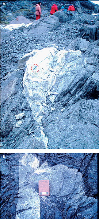
Fig. 50 Leucocratic centres in larger, zoned dykes. A: Felsic material in centre of a >20 m Kangâmiut dyke (ENE-trending) showing both intrusive relationship (front, left) and concordance (centre, right) with the main, mafic part of the dyke. North shore, mouth of Itillip Ilua (pen in red dashed circle measures 13 cm). B: Centre of a 10 m wide Kangâmiut dyke (E–W-trending) showing an irregular layer of leucocratic, coarse-grained material. Late-intrusive nature of the felsic material is seen by the discordant and concordant relationships with the main mafic dyke body, and by the penetrative foliation overprinting both lithologies. Eqalugaarsuit, north shore Itillip Ilua. Notebook is 13 x 18 cm.
4.2 Geochemistry of Kangâmiut dykes in the SNO and its southern foreland
In this Section we consider whether any systematic compositional variations exist among the dykes from Maniitsoq to Ikertooq. The discussion is based on a compilation of Kangâmiut dyke chemical analyses, including major and trace elements, and selected rare-earth element (REE) data for >400 dykes where location information is available (see Fig. 46 for locations and sources of data).
In Areas 01 to 08, the metamorphic overprints on the dykes vary from only minor hydration to strong recrystallisation, but igneous features are generally recognisable (see Chapter 5). This is not so in Area 10, where all dykes, along with their country rocks, are thoroughly recrystallised in amphibolite facies, and in Area 11, where dykes and their hosts are in granulite facies throughout. Area 09 represents a transitional zone between Areas 08 and 10. While our aim is to characterise any primary magmatic compositional variations, we acknowledge that penetrative amphibolite and granulite facies metamorphism is typically associated with enhanced mobility of certain elements (e.g. Bridgwater 1979; Rollinson 1993), so we expected to see these phenomena in Areas 10 and 11. We include these areas in our discussion, so that any patterns, trends or signatures which could be related to enhanced element mobility, may be identified. Such observations are discussed further in Chapter 7.
The main geochemical features of the Kangâmiut dykes were described by Windley (1970), Jack (1978), Korstgård (1980), Zeck & Kalsbeek (1981) and Bridgwater et al. (1995). In addition, petrogenetic studies were presented by Mayborn (2000), Cadman et al. (2001), Mayborn & Lesher (2004, 2006) and Mayborn et al. (2008).
The compositional variation shown by the dykes in the present data set clearly shows them to be sub-alkaline tholeiites (Fig. 51), characterised by an overall Fe enrichment pattern. The higher SiO2 values (basaltic andesites: 52–56%; andesites: >56%) represent the leucocratic centres of larger dykes described previously. Despite the compositional differences, Mayborn et al. (2008) concluded that the late-stage andesitic components of the dykes were the products of mixing evolved Kangâmiut dyke magma with small amounts of partial mantle melts (see also Section 4.1).
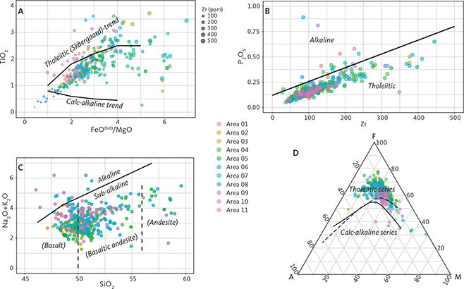
Fig. 51 Bulk-rock compositional variations and classification of Kangâmiut dykes. A: FeO(tot)/MgO vs. TiO2 (wt%). Composition of Kangâmiut dykes compared to typical tholeiitic and calc-alkaline trends (from Miyashiro 1974). The differentiation recorded by increasing x- and y-axis values is also shown by concomitant increases in Zr (ppm; as indicated by circle size). B: Zr (ppm) vs. P2O5 (wt%; after Winchester & Floyd 1977). A clear tholeiitic trend is shown. C: SiO2 (wt%) vs. K2O+Na2O (wt%). Most Kangâmiut dykes have low alkali content and SiO2 between 48% and 55% and so plot within the sub-alkaline fields of basalts and basaltic andesites. Most of the data points with higher SiO2 values extending into andesites, stem from leucocratic centres of wider dykes (see text for discussion). These higher SiO2 values also correspond to the higher FeO(tot)/MgO values (>4.5; panel A) and to the higher Zr values (>250 ppm; panel B). Boundaries and fields from Irvine & Baragar (1971). D: Kangâmiut dykes show the Fe-enrichment trend typical of the tholeiitic series of basic rocks. Solid dividing line from Irvine & Baragar (1971), stippled line from Kuno (1968). A: K2O+Na2O, F: FeO(tot), M: MgO, all wt%.
Based on mixing models involving Nd and Sr isotopes, Mayborn et al. (2008) show that the Kangâmiut precursor magma experienced only minor (≤8%) crustal contamination during differentiation at depth. Similar results were reported by Cadman et al. (2001), who additionally suggested that while the chemical evolution of the magma was controlled by clinopyroxene-plagioclase fractionation, later stage involvement of amphibole as a fractionating phase might have been important locally. In contrast, Mayborn & Lesher (2006) showed that amphibole was likely not a primary fractionating phase, and instead described the amphibole occurrences similar to the one shown in Fig. 47A, as a “late-stage magmatic phase”. Both studies emphasised, based on REE considerations, the lack of firm evidence for garnet being part of the fractionating assemblage.
Molecular proportion diagrams (i.e. Pearce diagrams; Pearce 1968, 1970) have been criticised for potentially yielding spurious results when used to test predictions for the identity of fractionating phases of an evolving magma (e.g. Rollinson 1993). None-the-less we feel that their usage here, to underscore the homogeneity of the present data set, is justified. Figure 52 shows that similar, if not identical, assemblages of fractionating phases, characterise the dyke data from across a wide study area and are thereby consistent with a common differentiation process and parent for all dykes. The figure also includes data from orthopyroxene-bearing noritic dykes from SW Greenland (Bridgwater et al. 1995), which display distinctly different trends than the Kangâmiut dykes.
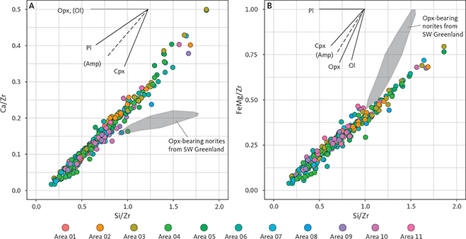
Fig. 52 Compositional variations and fractionation trends of Kangâmiut dykes. A: Pearce-type diagram (Si/Zr vs. Ca/Zr) showing bulk compositional effects of extracting precipitating phases. Vectors of orthopyroxene, olivine, plagioclase, amphibole and clinopyroxene are based on average compositions of these phases in this study. Trend is clearly consistent with compositional variations caused by a constant precipitating mineral assemblage (mainly plagioclase, clinopyroxene), throughout differentiation. Calculation of variables follows Pearce (1968). B: Pearce-type diagram for Si/Zr vs. FeMg/Zr, where FeMg is the sum of the molecular proportions of MgO and FeO(tot), following Pearce (1968). As in panel A, the data display a consistent trend. Grey shading: data from orthopyroxene-bearing norites in SW Greenland (Bridgwater et al. 1995), which clearly show a distinctly different trend. Opx: orthopyroxene. Ol: olivine. Pl: plagioclase. Amp: amphibole. Cpx: clinopyroxene.
In cross-plots of MgO vs. other major oxides (Fig. 53), it is also clear that clinopyroxene and plagioclase are the dominant precipitating phases. At higher MgO values, Al2O3 broadly decreases with decreasing MgO suggesting that both clinopyroxene and plagioclase fractionated. Meanwhile, the scattered increase in Al2O3 at lower MgO values (<3% MgO) suggests that plagioclase was less important at this stage. The strong positive correlation between MgO and CaO indicates that both plagioclase and clinopyroxene fractionated. In addition, we observe decreasing values in TiO2 and FeO(tot) with decreasing MgO below 4.5–5% MgO, suggesting that ilmenite enters the precipitating assemblage around those values, as noted by Mayborn & Lesher (2006). The only elements that may show scatter attributable to mobility during metamorphism are K and Na (see also Section 7.1). The subtle trends seen in MgO vs. K2O are further discussed in Section 7.1.
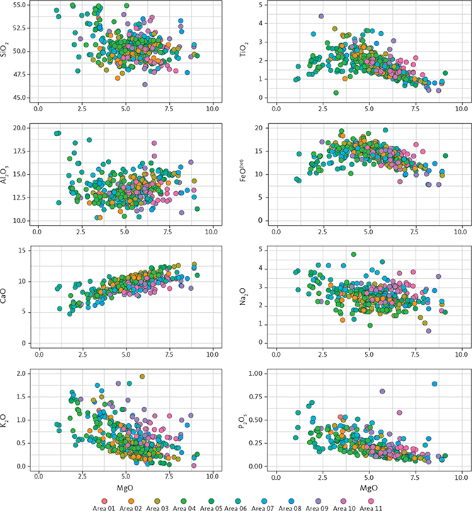
Fig. 53 MgO vs. major oxides for the Kangâmiut dykes (all wt%). The distinct trends seen in MgO vs. TiO2 and MgO vs. FeO(tot) suggest that ilmenite enters the precipitating phase assemblage around MgO = 4.5%. Note how alkalis (K2O, Na2O) and P2O5 behave as incompatible elements, whereas CaO and Al2O3 show the most distinct depletion with decreasing MgO.
A few of the outliers seen in Fig. 52 are also identified in Fig. 54, which shows MgO vs. CaO/Al2O3. While none of these elements are expected to show elevated mobility during metamorphism, the cross-plot may isolate dykes of different initial compositions. The overwhelming majority of analyses plot along a trend with fractionation of plagioclase and clinopyroxene (Mayborn 2000). However, along with the scatter, there are a few dykes with higher MgO or lower CaO/Al2O3 values that stand out. By isolating data from each of the 11 areas, we find that the data in Fig. 54 cluster around two dominant trends (determined visually). With decreasing MgO, data points follow the broad trend 1 until MgO reaches 4–5% and then shifts to the slightly steeper and better-defined trend 2 (Fig. 54). This happens to coincide with the trends in both the MgO vs. TiO2 and MgO vs. FeO(tot) plots (Fig. 53), where these shifts were interpreted to indicate that ilmenite became a significant part of the fractionating assemblage.
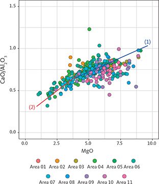
Fig. 54 MgO vs. CaO/Al2O3 (wt%). Data points outline a cluster showing decreasing MgO with decreasing CaO/Al2O3 with fractionation of both plagioclase and clinopyroxene (Mayborn 2000). A number of analyses with MgO > 5% fall below trend line (1) and come from E–W-trending dykes (Mayborn 2000; Areas 05 and 06) and from E–W-trending dykes in the northern areas (Area 08–11). (1): trend line 1. (2): trend line 2.
The few data points falling below trend 1 at MgO >5% deserve some attention. Five orthopyroxene-bearing, E–W-trending dykes from Mayborn (2000) come from Area 05 and 06 and plot at slightly higher MgO and lower CaO/Al2O3 values than the main cluster. The remaining outliers are from the northern areas (Area 08–11) from E–W-trending dykes also with higher MgO content. These may have carried primary orthopyroxene, but due to later metamorphic overprints, none are preserved.
It is worth reiterating, that while Figs 51–54 reflect some compositional variations in the data set, there is no evidence that any of the dykes initially had noritic compositions as seen in many dykes in SW Greenland (e.g. Bridgwater et al. 1995).
As mentioned previously, some of the wider Kangâmiut dykes display a visible mineralogical zoning from margin to centre, with finer-grained, sub-ophitic margins and coarser-grained, often leucocratic, centres. To assess the bulk chemical variations associated with this zoning, we have assembled a collection of dykes from which margin to centre sampling traverses were available (Fig. 55). Each block of data (4 to 9 samples) represents a traverse from margin (left) to centre (right) of a wide (>20 m) dyke. Several show subtle decreases in magnesium number (Mg#) and increases in Zr, from dyke margins to centres, in accordance with the fractionation trend previously described for the swarm as a whole. Some dykes, however, display little variation across a dyke, while a few even show a compositional asymmetry, with lower Mg# and higher Zr away from the dyke centre.
![Click to Enlarge View Fig. 55 Chemical variations for Zr (ppm) and Mg# from margins to centres of selected Kangâmiut dykes. Mg#: magnesium number, calculated as [MgO]/([MgO]+[FeO(tot)]) × 100, where [ ] indicates molecular proportions. Dyke orientation (black lines) and thickness (in m) are shown where available. Data sources: H: Hansen (1989). W: Windley (1970). B: Bridgwater (unpublished data). M: Mayborn (2000). K: Korstgård (1980). Each block of data separated by vertical stippled lines represents a single dyke sampled from margin (left) to centre (right). Some dykes show normal fractionation trends from margin to centre (decreasing Mg# and increasing Zr, for example the first dyke in Area 02 and the rightmost dyke in Area 04). Other dykes show a more asymmetric distribution where most fractionated material is encountered away from the centre (for example the second dyke in Area 04). Remaining dykes show no signs of any margin to centre variations (for example the first dyke in Area 05). For all dykes and samples, Mg# and Zr show opposite trends.](https://geusbulletin.org/index.php/geusb/article/download/8312/version/2808/14483/50037/8312_F0055.jpg)
Fig. 55 Chemical variations for Zr (ppm) and Mg# from margins to centres of selected Kangâmiut dykes. Mg#: magnesium number, calculated as [MgO]/([MgO]+[FeO(tot)]) × 100, where [ ] indicates molecular proportions. Dyke orientation (black lines) and thickness (in m) are shown where available. Data sources: H: Hansen (1989). W: Windley (1970). B: Bridgwater (unpublished data). M: Mayborn (2000). K: Korstgård (1980). Each block of data separated by vertical stippled lines represents a single dyke sampled from margin (left) to centre (right). Some dykes show normal fractionation trends from margin to centre (decreasing Mg# and increasing Zr, for example the first dyke in Area 02 and the rightmost dyke in Area 04). Other dykes show a more asymmetric distribution where most fractionated material is encountered away from the centre (for example the second dyke in Area 04). Remaining dykes show no signs of any margin to centre variations (for example the first dyke in Area 05). For all dykes and samples, Mg# and Zr show opposite trends.
The overall compositional homogeneity and predictability of the data set are also shown in a multielement diagram (Fig. 56A). In this figure the trace element concentrations are normalised to primitive mantle values (from McDonough & Sun 1995) and arranged from left to right in order of increasing compatibility in a small fraction melt of the mantle (e.g. Thompson 1982; Rollinson 1993). For simplicity, only mean values from each area are shown on a background of the distribution of results from all samples. The number of samples per area ranges from 5 (Area 01) to 62 (Area 6) for a total of 239 samples.
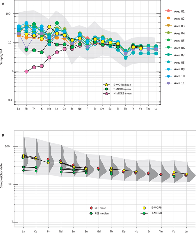
Fig. 56 Trace and rare earth element (REE) characteristics of Kangâmiut dykes. Data sources in Fig. 46 and Supplementary File S1. A: Multi-element plot for Kangâmiut dykes from Areas 01 to 11 normalised to PM (primitive mantle; values from McDonough & Sun 1995). For simplicity, only mean values of analyses from each area are displayed. Light grey shading: range of all data (n = 239). Shown are the mean values of enriched-, transitional- and normal-mid-ocean ridge basalt (E-MORB, T-MORB, N-MORB, respectively, from Hémond et al. 2006). A strong overlap with E-MORB is noted. B: REE plot of Kangâmiut dykes normalised to chondrite (normalisation values from McDonough & Sun 1995). Rather than displaying all 136 samples, we show the density distribution (dark grey shading) for each normalised REE, thus clearly representing the wider range of values for light REE (LREE) and narrow range for Heavy REE (HREE). Red diamonds: mean of each normalised element. Green diamonds: median. Light grey shading: range of all data (n = 136). The mean and median values of LREEs diverge according to the variable enrichment of these elements. The data showed no discernible variations between areas, so they are displayed together here. E-MORB and T-MORB are individual analyses from Hémond et al. (2006) and Waters et al. (2011), respectively.
The gentle, downward trend from the traditionally more mobile and incompatible elements in Fig. 56A (left) and towards the increasing compatibility of the immobile elements (right) is typical of other dyke swarms in continental settings and flood basalts (e.g. Cadman et al. 2001). This ‘crustal’ signature is distinct from that of more depleted normal mid-ocean ridge basalts (N-MORB) and even transitional mid-ocean ridge basalts (T-MORB) from other oceanic settings (e.g. Rollinson 1993). However, the signature is quite similar to those of more enriched and transitional MORBs (E-MORB and T-MORB, respectively; see Fig. 56A) with one exception being the negative Nb anomaly seen in all the dykes. Nb depletion typically reflects subduction-related settings, but as that is unlikely for the Kangâmiut dykes, the signature must stem from interaction with the continental crust.
The consistency of the patterns for both mobile and immobile elements is also an indication that regionally, dykes have escaped significant element remobilisation as a result of metamorphism (except for Rb in Area 11, see Chapter 7). In addition, the similarity to E-MORBs strongly suggest an origin in a rift-like tectonic environment in a constructive plate-margin setting. In Chapter 7, we address any compositional changes that may have accompanied the penetrative amphibolite and granulite facies metamorphism of dykes and their country rocks in the northern part of Itillip Ilua – Ikertooq (Areas 08–11) as well as the implications of the tectonic settings alluded to by the trace element patterns.
The geochemical uniformity among the members of the Kangâmiut dyke swarm is also evident in the rare earth element (REE) patterns (Fig. 56B). Of the 203 samples with REE data, we have selected 145 that had a complete set of data (from La to Lu). Additionally, we omitted nine samples, from which field evidence may not belong to the main Kangâmiut swarm. The chondrite-normalised patterns exhibit very shallow to moderate slopes. For most samples, the steeper slopes are commonly associated with greater enrichment in the light REE (LREE; Fig. 56, left side) but only slight increase in the heavy REE (HREE; Fig. 56, right side).
The magnitude of enrichment appears to be correlated with the location within the dyke where the sample was collected. For a few dykes, sampling traverses from margin to centre were available, and the samples collected near dyke margins consistently showed lower enrichments of LREE than samples collected near dyke centres. This pattern is consistent with crystallisation of the dyke initiating at the dyke margins with no or minor enrichment, and slight to moderate progressive enrichment towards the centre, as incompatible LREEs become more concentrated in the residual magma. As shown by Mayborn et al. (2008), the dykes with leucocratic centres of andesitic composition typically displays such enrichment patterns.
The nine samples omitted from this analysis had consistently steeper slopes that cross-cut the slopes of the remainder of samples. These samples are compositionally distinct from the other dykes, are consistently more Mg-rich and likely represent separate intrusions.
The overall gently sloping REE pattern of most dykes parallels that of classic E-MORB (Saccani et al. 2004; Hémond et al. 2006; Li et al. 2015). As shown in Fig. 56B, the REE patterns for the Kangâmiut dyke data set are indistinguishable from those of certain E-MORB samples from the Mid-Atlantic Ridge and show some overlap with T-MORB (Hémond et al. 2006). Saccani et al. (2004) argued that such characteristics in basaltic dykes intruded into continental crust are consistent with a tectonic model of rifting involving magma genesis affected by mantle plume interaction with MORB-type asthenospheric mantle. Similar to that shown for the trace element distribution described here, the strong correlation of the Kangâmiut dyke REE patterns with E-MORB lends support to a model in which the Kangâmiut dykes represent the magmatic emplacement of rift volcanics during continental extension or break-up.
5 Metamorphic overprints on Kangâmiut dykes from Maniitsoq to Itillip Ilua
The structural and metamorphic evolution of the Kangâmiut dykes and their host rocks in the region between Itillip Ilua and Ikertooq differs in many respects from the changes observed between Maniitsoq and Itillip Ilua and will therefore be described separately (Chapter 6).
Previous studies described the Kangâmiut dykes in the southern foreland as largely pristine and unaffected by Nagssugtoqidian orogenesis, based on the field appearance of the dykes. The widespread occurrence of garnets was assigned to thermal effects from the slowly cooling basic magma (e.g. Jack 1978). Ramberg (1949) and Noe-Nygaard & Ramberg (1961b) only briefly describe the conversion of the Kangâmiut dykes to schistose amphibolites along Kangerlussuaq. Dykes from the Maniitsoq area, consisting of dolerite at the margins and garnet amphibolite in the centre of larger dykes, are described by Windley (1970).
In the Inussuttusup Tunua area (Fig. 2), the metamorphic overprints are recognised as being more significant. Jack (1978) described a suite of corona structures in the Kangâmiut dykes in detail and concluded that these metamorphic features were a result of “autometamorphism”, as the dykes cooled slowly from their consolidation temperature (c. 900°C) to ambient country rock temperatures (500–700°C).
We demonstrate that there is not a gradual increase in metamorphic grade recorded by the dykes from Maniitsoq to Itillip Ilua. Rather that most of the features listed here, from minor hydration of igneous assemblages to partial conversion of dykes to amphibolite facies amphibolites and garnet amphibolites can be observed throughout that area. Only in the area north of Itillip Ilua (Fig. 2) does Nagssugtoqidian metamorphism and deformation result in the gradual to wholesale conversion of dykes to amphibolites, culminating in Ikertooq where the metamorphic grade recorded by the dykes and their hosts reach granulite facies.
The descriptions in the following sections are arranged in order of increasing signs of metamorphic overprints (i.e. any post-emplacement modifications of the original igneous mineralogy) as observed across the study area. The fully recrystallised dykes in amphibolite and granulite facies from Saqqap Kangerluarsua to Maligiaq (Fig. 2) are treated in Chapter 6.
5.1 Amphibole rims on ilmenite
One of the first signs of hydration of the igneous mineral assemblage (clinopyroxene, plagioclase, ilmenite, ±amphibole, ±orthopyroxene, see also Section 4.2) is the formation of thin, blue-green amphibole rims on ilmenite. Figure 56 shows various stages of the development of amphibole rims. These rims typically occur where ilmenite is in contact with plagioclase, whereas ilmenites in contact with clinopyroxene may not show amphibole rims. Compositionally, these amphiboles are “ferro-pargasites” (following the nomenclature of Hawthorne et al. 2012; see also Fig. 48A). Adjacent plagioclase is clearly involved in the amphibole-forming reactions, as anorthite content in plagioclase (An) is lowered drastically along the amphibole rims (An20–25 vs. An60 in cores of igneous plagioclase). As seen in Fig. 57, these amphibole rims occur both in fine-grained samples from marginal chills and from coarser-grained parts of dykes with well-developed ophitic textures. It is notable, that in samples with only amphibole rims on ilmenites, the clinopyroxenes appear fresh, and have not been replaced, even partially, by amphiboles.
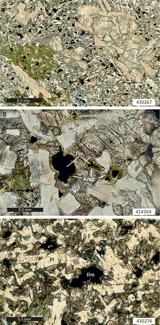
Fig. 57 Early metamorphic overprints of amphibole rims on ilmenite. A: Chilled margin of 30 m wide Kangâmiut dyke. Primary amphibole and clinopyroxene overgrowing a fine-grained matrix of plagioclase, clinopyroxene and ilmenite. Example of incipient formation of thin amphibole rims on ilmenite shown in circle. 1 nicol. Sample 430267. South shore, mouth of Kangerlussuatsiaq. B: Margin of 40 m wide dyke with pronounced podding geometry. Brown-green amphibole overgrowing ilmenite grains, mainly at the expense of adjacent plagioclase. Neighbouring clinopyroxenes show no amphibole rims. 1 nicol. Sample 414304. North shore, mouth of Itillip Ilua. C: Fine-grained NE-trending dyke sampled a few centimetres from contact to older, coarse-grained E–W-trending dyke (outcrop shown in Fig. 10C). Blue-green amphibole rims on ilmenites. 1 nicol. Sample 430274. South shore, mouth of Kangerlussuatsiaq. Amp: amphibole. Cpx: clinopyroxene. Ilm: ilmenite. Pl: plagioclase.
5.2 Amphibole rims on clinopyroxene
Further hydration is recorded by the formation of a more extensive network of blue-green to green amphibole rims on igneous clinopyroxenes (Fig. 58). These rims are never seen in microstructural settings where adjacent ilmenites have no rims and are thus interpreted to represent a further step in the metamorphic development. As in the case of amphibole rims on ilmenites, the participation of plagioclase in this amphibole-forming reaction is shown by the lower An contents in adjacent plagioclase, and the disturbance of the igneous zoning patterns as seen in the microscope. The continued growth of amphibole in the rims appear to largely take place at the expense of plagioclase (Fig. 58). These amphibole rims also seem to develop on clinopyroxenes that have undergone partial or full replacement by amphiboles (Fig. 58B, C), suggesting that the alteration of clinopyroxenes was initiated prior to rim development. Igneous orthopyroxenes are more resistant to alteration than coexisting clinopyroxenes, and also appears to have a less well-developed amphibole rims (Fig. 58B).
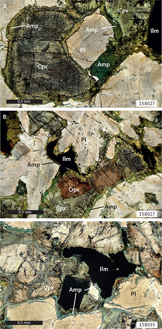
Fig. 58 Early metamorphic overprints: amphibole rims on ilmenite and clinopyroxene. A: Green amphibole rims on ilmenite (top right) and clinopyroxene. Locally, the plagioclase rims adjacent to amphibole rims are brighter and free from inclusions. Centre of NNE-trending dyke. 1 nicol. Sample 158027. Southern Inussuttusup Tunua. B: Thin, green amphibole rims on ilmenite (centre), clinopyroxene and orthopyroxene. Centre of NNE-trending dyke. 1 nicol. Sample 158027. Southern Inussuttusup Tunua. C: Thin, blue-green amphibole rims on ilmenite and clinopyroxene. Locally, amphiboles also grow on internal boundaries in clinopyroxene aggregates. Amphiboles may or may not grow along ilmenite–clinopyroxene interfaces, possibly reflecting lack of access to necessary reactants (i.e. fluid, plagioclase). 1 nicol. Sample 158035, 2 km north of Kangaamiut. Amp: amphibole. Cpx: clinopyroxene. Ilm: ilmenite. Opx: orthopyroxene. Pl: plagioclase.
5.3 Partial to complete replacement of clinopyroxene by amphibole
Along with the growth of amphibole along the margins, the internal parts of clinopyroxenes may be partially to completely replaced by amphiboles, typically with a greenish colour (various examples shown in Fig. 59). Replacement occurs initially along cracks, fractures and internal grain boundaries in clinopyroxene aggregates. Ilmenite grains may be seen in or near the boundary between newly formed amphibole and clinopyroxene, indicating that ilmenite participated in the amphibole-forming reaction. In the final stages, the entire grain is replaced with a quartz inclusion-filled, poikilitic, green to dark green amphibole (Fig. 59D). The original amphibole rim, which initially surrounded the igneous clinopyroxene, is in many cases still visible after complete replacement of the inner parts (Fig. 59D). Where the initial amphibole rim is typically composed of thin, radiating crystals perpendicular to the clinopyroxene grain boundary (see Fig. 58), the later rim is often less distinct and recrystallised to a polygonal layer (Fig. 59C). As mentioned above, the relative timing and progress of clinopyroxene conversion to amphibole varies significantly between samples, and even within a thin section. In some samples, well-developed garnet rims occur on partially converted clinopyroxenes, whereas in others, the early thin amphibole rims surround completely amphibolitised clinopyroxene grains or aggregates. We suspect that subtle variations of fluid accessibility and pressure–temperature (P–T) conditions are responsible for these varied developments of whole vs. partial amphibolitisation.
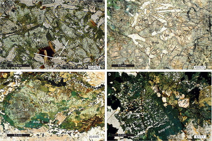
Fig. 59 Early metamorphic overprints: partial to complete replacement of clinopyroxene by amphibole. A: Centre of 1 m wide pod in Kangâmiut dyke. Green amphibole grows on all clinopyroxene–plagioclase and clinopyroxene–clinopyroxene contacts. 1 nicol. Sample 414429. Equalugaarsuit, north shore Itillip Ilua. B: Coarse-grained part of 50 m wide N–S-trending dyke. Clinopyroxene aggregate, partially replaced by pale-green amphiboles along rims and along internal boundaries. 1 nicol. Sample 430275. South shore, mouth of Kangerlussuatsiaq. C: 70 m wide, foliated, recrystallised and zoned NE-trending dyke. Clinopyroxene with rims of green amphibole (Amp-1) and advanced internal replacement by lighter-green amphiboles (Amp-2). 1 nicol. Sample 414445. South shore, mouth of Itillip Ilua. D: 48 m wide Kangâmiut dyke showing pronounced compositional zoning. Sample from the central part of dyke. Advanced replacement of clinopyroxene by recrystallised, green amphibole and quartz in a poikilitic aggregate. Euhedral garnets grow in parts of the amphibole rim. 1 nicol. Sample 87777. Coast just north-east of Sermersuut. Amp: amphibole. Amp-rim: amphibole rim. Cpx: clinopyroxene. Grt: garnet. Qtz: quartz.
5.4 Epidote growth in plagioclase
Epidote growth in igneous plagioclase is mainly observed in the southern part of the study area, however, as the epidotes vary substantially in both size and crystal form, it is possible that very small grains were occasionally overlooked under the microscope and are thus more widespread. Well-developed, large (up to 0.3 mm) lath-shaped crystals develop in the central, more Ca-rich parts of the igneous plagioclase (Fig. 60A, B). Where subsequent recrystallisation of the plagioclase has occurred, the clusters of epidotes mimic the original shapes of the igneous plagioclases (Fig. 60B). The brownish dusting that is commonly observed in igneous plagioclases, presumably disseminated Fe oxides (see Figs 57, 58), tends to disappear in the vicinity of epidotes and may thus take part in the hydration reaction. Compositionally, the epidotes show only minor variation and are either ‘epidotes’ or ‘clinozoisites’, depending on whether Fe3+ or Al3+, respectively, is the dominant cation in the M3 site (following the classification of Armbruster et al. 2006).
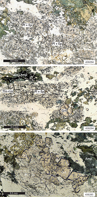
Fig. 60 Early metamorphic overprints of epidote growth in plagioclase. A: Coarse-grained, central mafic part of 40 m wide composite Kangâmiut dyke. Randomly orientated epidote laths in plagioclase. The density of epidote outlines compositional zoning patterns in original, igneous plagioclase. Epidote-rich plagioclases separated by inclusion-free plagioclase. 1 nicol. Ungusivik island, 8 km south of mouth of Kangerlussuaq. B: Same sample as panel A. Here, garnet has entered the assemblage. Epidote clearly outlines compositional zoning pattern in plagioclase. Top left, skeletal ilmenite in amphibole suggests advanced replacement of ilmenite. Thin rims of titanite can be seen on the skeletal ilmenite. C: Garnet-bearing centre of 30 m wide NE-trending dyke. Euhedral garnet growing between plagioclase and amphibole, largely at the expense of plagioclase. Epidote needles in plagioclase show a wide range in size (0.01–0.1 mm). 1 nicol. South shore, mouth of Kangerlussuatsiaq. Amp: amphibole. Ep: epidote laths. Grt: garnet. Ilm: ilmenite. Pl: plagioclase. Ttn-rim: titanite rim.
5.5 Garnet growth on ilmenite and in amphibole rims on ilmenite
Coincident with the early stages of amphibole rims forming on clinopyroxenes, garnets begin to form along ilmenite rims (various stages of reaction progress shown in Fig. 61). In most cases, garnet growth is clearly replacing a pre-existing amphibole rim (Fig. 61), whereas in other cases, garnet develops directly at the ilmenite:plagioclase interface, with no remnants of amphibole. Considering that ilmenites without amphibole rims are rare among the least metamorphosed dykes, it is thought that garnet rims on ilmenite without amphibole reflect complete consumption of an earlier amphibole. Early garnets occur as fine-grained, inclusion-filled aggregates, and as garnet growth progresses in either setting, grains are increasingly inclusion-free and euhedral, especially in their outer rims against adjacent plagioclase. Figure 61D shows an example of a complex garnet rim along half the perimeter of an ilmenite. In this example the inner part of the rim is riddled with elongate grains of biotite and amphibole, all perpendicular to the ilmenite grain boundary, while the outer part consists of clear, inclusion-free euhedral garnet grains. Along the remainder of the ilmenite grain boundary, the amphibole rim has yet to be replaced. Compositionally, the garnets show minimal variation across the rim, while the varying mineralogy inside the rims suggests that a continuum of mineral reactions is responsible for the rim assemblages. At higher metamorphic grades, recorded in the area around Itillip Ilua, the garnet rims on ilmenites become even more complex. Figure 62 shows an example of complex garnet rims on some parts of the ilmenite grains, while other parts of the ilmenites and the adjacent clinopyroxene only display amphibole rims.
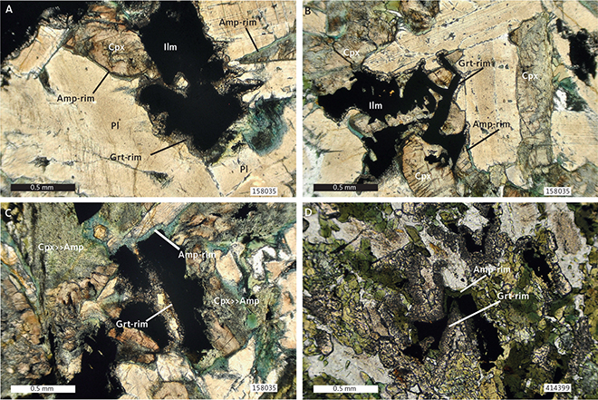
Fig. 61 Early metamorphic overprints of garnet growth on ilmenite. A: Delicate garnet rims along ilmenite–plagioclase interfaces and pale green amphibole rims between clinopyroxene and plagioclase. 1 nicol. Sample 158035. 2 km north of Kangaamiut. B: Same as panel A. Thin garnet rims between ilmenite and plagioclase. Amphibole rims on most clinopyroxene–plagioclase contacts. Around the perimeter of a plagioclase grain, garnet is encountered at ilmenite contacts, and amphibole at clinopyroxene contacts. Generally, no garnet or amphibole occur along ilmenite–clinopyroxene contacts. 1 nicol. Sample 158035. 2 km north of Kangaamiut. C: Similar to panels A and B, except that in this domain, clinopyroxenes are being replaced by amphiboles, both internally and along aggregate boundaries (Cpx>>Amp). Thin blue-green amphibole rims are developed between ilmenite and clinopyroxene. 1 nicol. Sample 158035, 2 km north of Kangaamiut. D: Margin of 10 m wide E–W-trending dyke in Itillip Ilua. Ilmenite has a green amphibole rim, which is being replaced locally by a garnet rim consisting of an inner, inclusion-filled rim, and an outer, euhedral rim protruding into neighbouring plagioclase. 1 nicol. Sample 414399. Eqalugaarsuit, north shore, Itillip Ilua. Amp: amphibole. Cpx: clinopyroxene. Grt: garnet. Ilm: ilmenite. Pl: plagioclase.
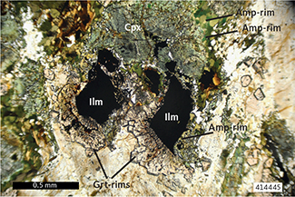
Fig. 62 A 70 m wide, foliated, recrystallised and zoned NE-trending dyke. Two ilmenite grains with complex garnet rims. Ilmenite to the right has an amphibole rim along its right side and a garnet rim along the rest of its perimeter. Inner garnet rim contains very fine-grained, radiating minerals (biotite, ilmenite), whereas the outer rim is inclusion-free and shows euhedral crystal faces protruding into plagioclase. The ilmenite to the left shows incipient skeletal texture in the upper right part of the grain and has a double rim of garnet towards the bottom and left. Inner rim and inner part of the outer rim contain thin, radiating inclusions, while the outer rim is inclusion-free with euhedral grains. Adjacent clinopyroxene has a recrystallised amphibole rim, but no garnets. 1 nicol. Sample 414445. South shore, mouth of Itillip Ilua. Amp: amphibole. Cpx: clinopyroxene. Grt: garnet. Ilm: Ilmenite.
5.6 Garnet growth in amphibole rims on clinopyroxene
Further progress of metamorphic overprinting is recorded by the growth of garnets in the amphibole rim surrounding clinopyroxene (Fig. 63, increased reaction progress from A to C). Most observations suggest that the garnet initially grows at the clinopyroxene-amphibole interface, mainly at the expense of amphibole. However, other geometries, for example garnet replacing the amphibole rim from the amphibole-plagioclase grain boundary and inwards, are also observed (Fig. 63B). Where amphiboles have been completely consumed, garnet grains form ‘atolls’ consisting of euhedral crystals, typically protruding into, and sometimes almost replacing the plagioclase (Fig. 63C). As noted earlier, the participation of plagioclase in these reactions is shown by the significant drop in An content adjacent to the garnets.
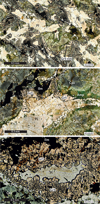
Fig. 63 Early metamorphic overprints of garnet growth in amphibole rims on clinopyroxene. A: Centre of 1.5 m wide dyke. Advanced growth of garnet on ilmenite. Amphibole rims on all clinopyroxene, and locally garnet, partly or entirely replaces amphibole. Outer part of most garnet rims shows inclusion-free, euhedral growths into plagioclase. 1 nicol. Sample 414409. North shore, central part of Itillip Ilua. B: 70 m wide, foliated, recrystallised and zoned NE-trending dyke. Wide garnet rims on ilmenite and garnet growth in amphibole rims surrounding clinopyroxenes. 1 nicol. Sample 414445. South shore, mouth of Itillip Ilua. C: Garnet-bearing, leucocratic zone in coarse-grained dyke. Advanced growth of garnet on ilmenite and clinopyroxenes. Outermost rims are inclusion-free and euhedral. Sample 414411. North shore, central part of Itillip Ilua. Amp: amphibole. Cpx: clinopyroxene. Grt: garnet. Ilm: Ilmenite. Pl: plagioclase.
5.7 Titanite rims on ilmenite
In a few instances, narrow titanite rims have been observed on ilmenite (Fig. 60B). These ilmenites may display a pronounced skeletal habit (Fig. 64A), presumably reflecting the involvement of ilmenite in the amphibole and garnet forming mineral reactions as well as the formation of titanite. Skeletal ilmenites are also observed in situations where titanite rims are not developed and may similarly reflect the involvement of ilmenite in other metamorphic reactions. The examples in Figs 64A, B show skeletal ilmenites, with titanite overgrowths that in turn are overgrown by garnets, thus suggesting that the ilmenite–titanite transition predated garnet growth.

Fig. 64 Early metamorphic overprints of titanite rims on ilmenite. A: Garnet-bearing, leucocratic material from the centre of a large dyke. Skeletal ilmenite partially replaced by titanite along parallel planes. Ilmenite–titanite aggregate (red dashed line) completely overgrown by garnet. 1 nicol. Sample 414432. North shore, mouth of Itillip Ilua. B: Same sample as panel A, but with much more irregular geometry of titanite replacement and overgrowth of ilmenite. 1 nicol. Sample 414432. North shore, mouth of Itillip Ilua. Amp: amphibole. Grt: garnet. Ilm: Ilmenite. Ttn: titanite.
5.8 Disseminated garnet in dyke margins
In the fine-grained margins of some dykes, garnet-rich zones sometimes occur along what appears to be cracks or fractures, typically at a high angle to the dyke contact. The zones can be millimetre to centimetre in scale and can sometimes show curvature towards the margin reflecting an apparent sense of shear. Figure 65A shows an example of garnet-filled millimetre-scale veins at high angles to the contact. Towards the centre of the dyke, the bands are wider (millimetre–centimetre scale) and more diffuse (Fig. 65B). The central part of many dykes is coarser-grained garnet-amphibolite (Fig. 65C). In addition to garnet-filled veins, some dykes also show numerous 5–10 mm wide garnet clusters throughout their contact zones (see the lighter ‘spots’ in the darker bands in Fig. 65A). In thin section, these garnet-filled veins are relatively fine-grained (Fig. 66A) and composed of garnet and ilmenite and a very fine-grained matrix. The veins appear to truncate the primary sub-ophitic texture in the dyke margins without much interaction with the igneous mineralogy (Fig. 66A), at times surrounding ophitic igneous clinopyroxene aggregates entirely. Where coarser-grained dykes are invaded by the garnet-filled veins, the resultant texture is more diffuse, and the veins seem to advance along boundaries of the larger plagioclase and clinopyroxene grains (Fig. 66B). The timing of the formation of these garnet-rich veins, layers and clusters is most likely coincident with the overall metamorphic overprint seen in the dykes and it is thought that the garnet-filled veins utilised pre-existing structures and weaknesses as conduits when they propagated into the dykes.
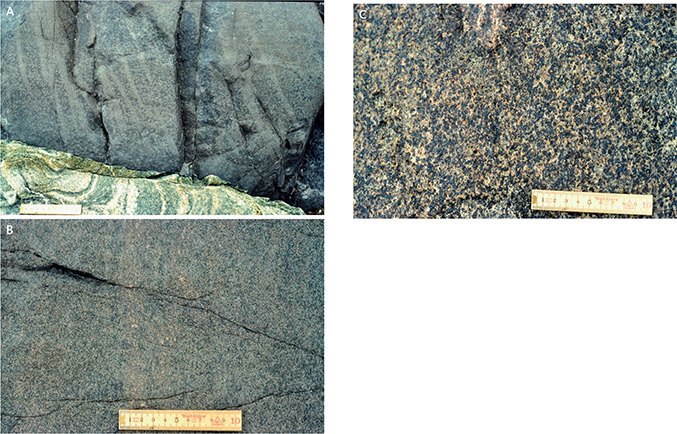
Fig. 65 Early metamorphic overprints of disseminated garnet in margins of dykes. A: Sharp contact between Kangâmiut dyke (upper part of image) and folded leucocratic host gneiss (lower part). Broadly parallel, non-continuous 1–2 cm wide, lighter, garnet-rich bands can be seen at a high angle to the dyke contact. Within darker bands, millimetre-scale, garnet-rich aggregates are widely distributed and appear as lighter grey dots. Eqalugaarsuit, north shore Itillip Ilua. B: Fine-grained dyke with primary compositional layering parallel to margin and accentuated by alternating garnet-rich (lighter brown bands) and amphibole-richer (darker colour) zones. Eqalugaarsuit, north shore Itillip Ilua. C: Detail of homogeneous, isotropic and coarse-grained part of dyke, made up of plagioclase (light coloured), amphibole (dark grey) and garnet (dark red specs). Eqalugaarsuit, north shore Itillip Ilua. Scale is 10 cm in all the figures.

Fig. 66 Early metamorphic overprints of disseminated garnet in margins of dykes. A: Fine-grained dyke margin with garnet-filled veins and bands. Partially altered clinopyroxene with recrystallised rims of brown-green amphibole. Irregular, discordant band of fine-grained aggregate of garnet and ilmenite cuts across the thin section (top right to lower left) 1 nicol. Sample 414433. North shore, mouth of Itillip Ilua. B: Margin of NNE-trending and 40 cm wide dyke. Igneous minerals and texture are largely preserved. A few clinopyroxenes have thin green amphibole rims. In diffuse, fine-grained aggregate (1–2 mm across), garnets overgrow all ilmenites and line most other grain boundaries. 1 nicol. Sample 414443. South shore, mouth of Itillip Ilua. Amp: amphibole. Cpx: clinopyroxene. Grt: garnet. Ilm: Ilmenite. Pl: plagioclase.
5.9 Distribution of metamorphic overprints from Maniitsoq to Itillip Ilua
The metamorphic features described above are schematically summarised in Fig. 67, which illustrates the mineralogical changes that occur at the igneous ilmenite–plagioclase and clinopyroxene–plagioclase boundaries, respectively. The progress of metamorphic overprints increases from left to right (more information in figure caption). In terms of reaction progress, it is notable, that reactions at the ilmenite-plagioclase boundaries appear to proceed before those at the clinopyroxene-plagioclase interfaces.
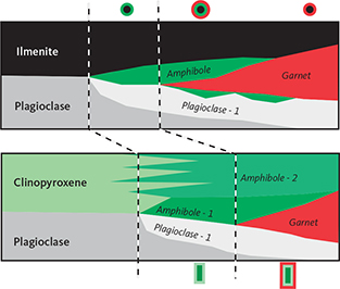
Fig. 67 Schematic to illustrate the metamorphic reactions that take place at ilmenite–plagioclase (top) and clinopyroxene–plagioclase (bottom) interfaces, with increasing degree of reaction progress from left to right. Note that both amphibole and garnet formation occur earlier along ilmenite than along clinopyroxene margins. Plagioclase: original igneous plagioclase with anorthite contents up to An60. Plagioclase-1: metamorphic plagioclase, initially participates in the amphibole-forming reactions and later in the garnet-forming process. Plagioclase-1 has much lower anorthite content (An20-30). Amphibole and Amphibole-1: first grow along ilmenite and clinopyroxene margins, respectively. Amphibole-2 is the result of replacement of the internal parts of clinopyroxene grains by amphiboles, typically along fractures, cleavage planes or in patches. Not shown is the epidote formation within plagioclases and titanite growth at the expense of ilmenite. Symbols above and below the diagram corresponds to the mineral assemblage symbols in Fig. 68.
Figure 68 shows the regional distribution of the metamorphic features described here and in Fig. 67. This compilation also includes a few observations from Hansen (1989) and from Mayborn (2000). As mentioned previously, the area from Maniitsoq to Itillip Ilua does not represent a simple, gradual progress in the metamorphic overprints, as schematically shown in Fig. 67. Rather it demonstrates that most of the features can be found throughout the area, clearly suggesting that whatever drove these metamorphic processes (pressure, temperature, availability of fluids) was heterogeneously distributed throughout this southern foreland region. The metamorphic drivers, their causes and the conditions under which they operated are further discussed in Chapter 9.
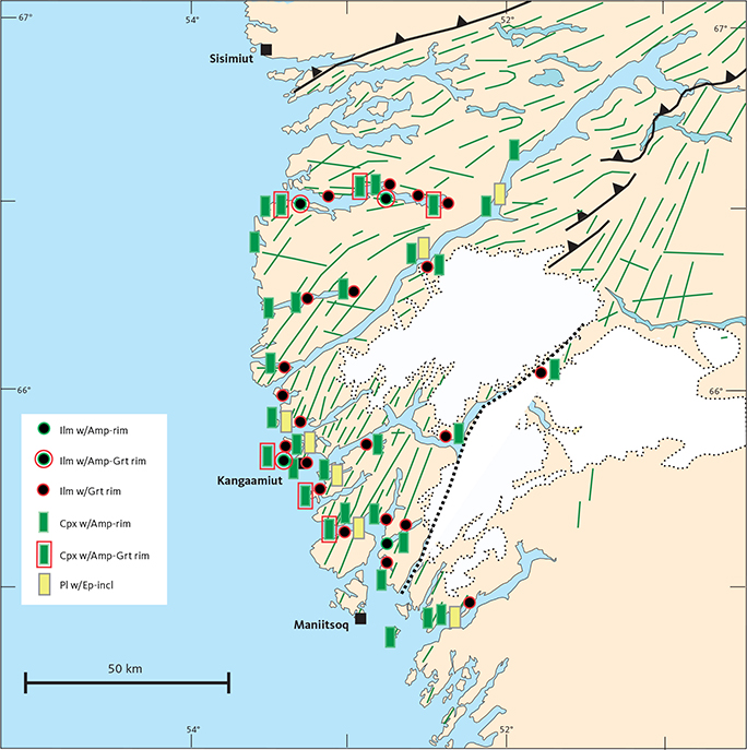
Fig. 68 Simplified map of the mineral assemblages described in Section 3.1 showing the distribution of observed metamorphic overprints at individual sample locations. See Fig. 1 for explanation of fault and dyke symbols and other place names. Mineral abbreviations follow Whitney & Evans (2010). Ilm w/Amp-rim: Ilmenite with amphibole rims. Ilm w/Amp-Grt rim: ilmenite with rims of amphibole and garnet. Ilm w/Grt rim: ilmenite with garnet rims. Cpx w/Amp-rim: clinopyroxene with amphibole rims. Cpx w/Amp-Grt rim: clinopyroxene with rims of amphibole and garnet. Pl w/Ep-incl: plagioclase with epidote inclusions.
A quantitative look at the variations of both igneous and metamorphic minerals from Maniitsoq to Itillip Ilua is illustrated in Fig. 49, which represents a compilation of all available modal analyses. Despite variability in terms of the detail and number of points analysed, and in accuracy when discriminating between igneous and metamorphic minerals, it is noteworthy how relatively little variation there is in the contents of both felsic (plagioclase + quartz) and mafic (pyroxenes + amphibole) minerals from Area 02 to Area 07. This underscores an earlier assertion based on bulk-rock chemistry, that the igneous precursors to these variably metamorphosed dykes were compositionally homogeneous on a regional scale. The modal variations shown in Fig. 49 are interpreted to reflect the very heterogeneous progress of reactions leading to the growth of amphibole rims on igneous minerals to the complete replacement of igneous phases. In Areas 09–11, all minerals are metamorphic. The volume of garnet increases from south to north and reaches a maximum of c. 10 vol.% in Areas 06 and 07, but then drastically decreases farther north, only to sporadically pick back up again in Area 11.
In Areas 08–11, the structural and metamorphic evolution of Kangâmiut dykes and their host rocks differs from the changes observed between Maniitsoq and Itillip Ilua and are treated separately next.
6 Deformation and metamorphism of dykes and country rocks from Saqqap Kangerluarsua to Maligiaq
6.1 Microstructural changes
The conversion of the dolerite dykes into metadykes or amphibolites can be observed south of Saqqap Kangerluarsua and especially in Qaqqatoqaq and along Itillip Ilua (Fig. 35). Here, every stage from unaltered dolerite dyke to metadyke is exposed. The conversion took place under varying degrees of deformation and although the final product is essentially the same, apart from variations in grain size and intensity of linear and planar fabric, there are some important differences in the paths taken by the dykes during their conversion into amphibolites. We tend to use metadyke and amphibolite synonymously, since metamorphosed basaltic dykes per definition are amphibolites. However, some amphibolites may have a different precursor (e.g. Leake 1964).
In this section, the dyke-to-metadyke conversion will be described in terms of accompanying changes in microstructure, including changes in shape and arrangement of crystals (Vernon 2004; Vernon & Clarke 2008), from a non-metamorphic microstructure to a granoblastic metamorphic microstructure. Two cases are considered: (1) microstructural changes in dykes metamorphosed during weak deformation, and (2) microstructural changes in dykes during strong deformation. Deformation here refers to deformation as observed in thin sections and not necessarily to deformation as seen from the geometry of the dyke body.
6.1.1 Dykes metamorphosed under weak deformation
In weakly deformed dykes, the changes in shape and arrangement of grains are exclusively associated with a change in the mineralogy of the dykes. The metamorphic overprints described in Chapter 5, mainly growth of amphibole and garnet, has little effect on the microstructure as the original igneous texture is still recognisable. Further growth of amphibole and garnet and recrystallisation of plagioclase, however, eventually alters the microstructure from a sub-ophitic grain-contact arrangement to a granoblastic (polygonal) grain-contact arrangement. Mineralogically speaking, the dykes are now amphibolites since they are composed of metamorphic minerals, even if the original sub-ophitic distribution of dark and light mineral phases may still be discernible. In the following sections, a few pertinent steps in this metamorphic transition are described and illustrated.
6.1.1.1 Igneous microstructure
The microstructures of undeformed and unmetamorphosed dykes range from fine-grained porphyritic to sub-ophitic or coarse-grained, almost granular. The porphyritic microstructure is usually found in the margins of larger dykes. The phenocrysts are typically An-rich and up to 1 mm long plagioclases. Less frequently, smaller clinopyroxene phenocrysts with irregular outlines occur. The matrix is fine-grained (< 0.05 mm) and consists of clinopyroxene, plagioclase, ilmenite, and primary amphibole. Examples of porphyritic microstructures are shown in Fig. 69. The most common microstructure is a sub-ophitic microstructure where plagioclase crystals penetrate but are not enclosed by pyroxenes. In coarse-grained varieties, the sizes of the plagioclase crystals vary between 0.2 and 2 mm (Fig. 70), whereas in fine-grained dolerites this range is 0.1–0.5 mm (Fig. 71).
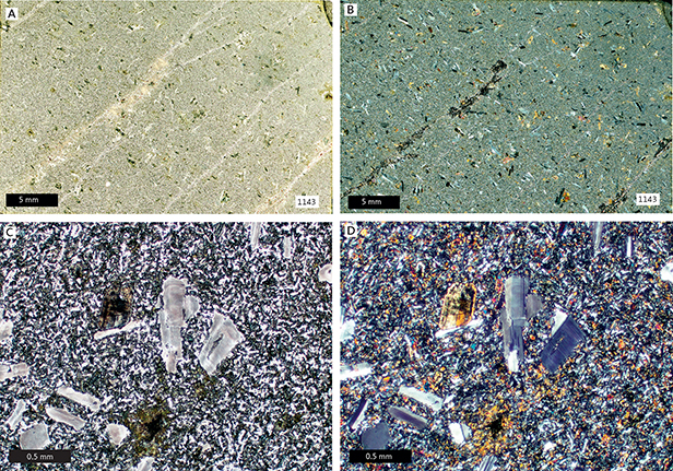
Fig. 69 Examples of porphyritic microstructure in fine-grained dyke. A, B: Porphyritic microstructure at dyke margin. C, D: Phenocrysts of plagioclase in a matrix of clinopyroxene, plagioclase, primary amphibole and ilmenite. A, C: 1 nicol. B, D: X nicols. Sample 1143. Outer Saqqap Kangerluarsua.
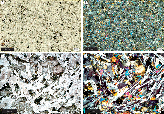
Fig. 70 Examples of sub-ophitic microstructure in coarse-grained dyke. A, B: Coarse-grained dyke with sub-ophitic microstructure. C, D: Laths of plagioclase with interstitial clinopyroxene. A, C: 1 nicol. B, D: X nicols. Sample 1332. South shore of central Itillip Ilua.
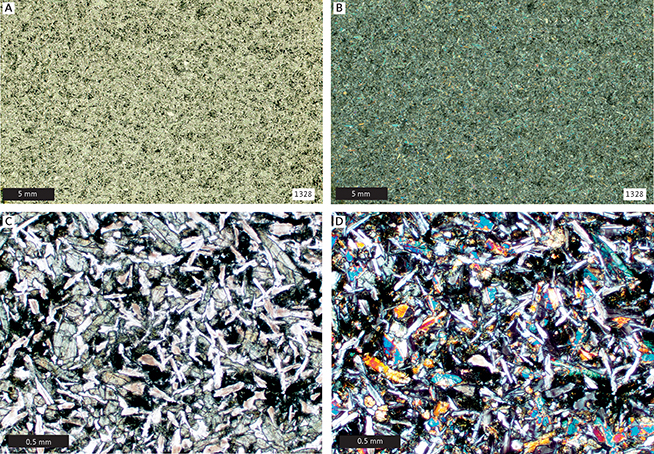
Fig. 71 Examples of sub-ophitic microstructure in fine-grained dyke. A, B: Fine-grained dyke with sub-ophitic microstructure. C, D: Laths of plagioclase with interstitial clinopyroxene. A, C: 1 nicol. B, D: X nicols. Sample 1328. South shore of central Itillip Ilua.
6.1.1.2 Incipient granoblastesis, no deformation
As described in Chapter 5, most Kangamiut dykes show signs of a metamorphic overprint, where amphiboles and garnets typically form at the expense of ilmenites and clinopyroxenes. Initially, the amphiboles are small, granoblastic crystals without any preferred shape orientation or pleochroism. Plagioclases becomes clouded (e.g. Figs 57B, 58A–C, 69, 70) and small, clear, granoblastic plagioclase crystals may start to develop around plagioclase laths and along plagioclase-plagioclase grain contacts. Throughout these mineralogical adjustments, the igneous sub-ophitic microstructure remains well preserved.
6.1.1.3 Intermediate granoblastesis, no deformation
At an intermediate stage of metamorphism, all clinopyroxene crystals are surrounded by rims of small, granoblastic amphibole crystals (Fig. 72C). This gives the rock a darker appearance in hand specimen, while in thin section, sub-ophitic microstructures become less distinct (Fig. 72A, B). At this stage, plagioclase crystals are surrounded by small new plagioclase crystals, ranging in size from 0.05 mm to 0.2 mm (Fig. 72A, B). This stage is also characterised by widespread development of garnet, which has now grown to a size of c. 0.2 mm. While approximately half of the crystals in these rocks are granoblastic, the distribution of light and dark minerals is still reminiscent of the original sub-ophitic microstructure (Fig. 72B).
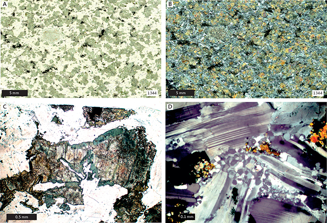
Fig. 72 Preserved sub-ophitic microstructure in dyke that is partly converted into a metadyke. A: 1 nicol. B: X nicols. C: 1 nicol, igneous clinopyroxene rimmed by amphibole. D: X nicols, small granular metamorphic plagioclase grains at igneous plagioclase interfaces. Sample 1344. South shore of central Itillip Ilua.
6.1.1.4 Advanced granoblastesis, no deformation
All igneous clinopyroxene has disappeared at this advanced stage of metamorphism (Fig. 73A, B). The amphiboles along the rims of former clinopyroxenes have now grown to larger granoblastic crystals, while their central part consists of aggregates of amphiboles and quartz (Fig. 73C, D). Most of the igneous plagioclase laths have also been replaced by smaller polygonal crystals, which have started to coalesce into larger crystals. In fine-grained dykes, mafic phases now consist of granoblastic aggregates of amphibole, garnet and ilmenite (Fig. 74). A few igneous phenocrysts of plagioclase or clinopyroxene or both may survive this transformation but are strongly corroded. Otherwise, these igneous laths are also converted into polygonal grains. Sample 1286, in Fig. 75, shows the final product of granoblastesis within a dyke with only a subtle indication of a planar fabric. Although completely recrystallised, it clearly preserves the original sub-ophitic distribution of felsic and mafic phases. This is not as apparent in sample 1288 (Fig. 75).
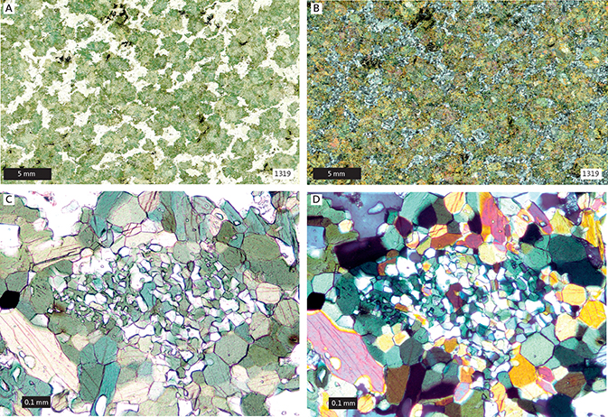
Fig. 73 A dyke in which most clinopyroxene crystals have been replaced by amphibole. A: 1 nicol. B: X nicols. Original igneous distribution of plagioclase still preserved. Note sieve hornblende (aggregate of amphibole and quartz replacing clinopyroxene). C: 1 nicol. D: X nicols. Sample 1319. North shore of central Itillip Ilua.
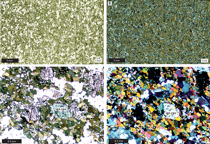
Fig. 74 A fine-grained dyke where most igneous minerals have been replaced by the metamorphic minerals, amphibole, garnet and plagioclase. Some igneous clinopyroxene (ign cpx) grains have survived. A, C: 1 nicol. B, D: X nicols. Sample 1316, north shore of central Itillip Ilua.
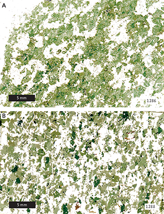
Fig. 75 A completely recrystallised dykes with a faint planar fabric. A: sample 1286. Partly igneous distribution of mineral phases. B: sample 1288. Igneous distribution of mineral phases can hardly be distinguished. Both 1 nicol. Qaqqatoqaq.
6.1.2 Dykes metamorphosed under strong deformation
The conversion of dykes into metadykes involves simultaneous deformation, as evidenced by the development of a strong directional fabric in the rocks, partially defined by metamorphic minerals. Several steps, involving various degrees of deformation and recrystallisation could be outlined, but only two cases are described and illustrated below: (1) deformation involving original igneous minerals and (2) deformation accompanied by complete recrystallisation.
6.1.2.1 Incipient granoblastesis, strong deformation
A directional fabric is produced through the development of elongate aggregates of plagioclase and mafic minerals. Most plagioclases break down to smaller equidimensional grains. Small garnets and amphiboles develop together with ilmenite and form elongate trails that define the directional fabric (Fig. 76). In contrast to dykes that have been metamorphosed without much deformation, the igneous clinopyroxenes within strongly deformed dykes often survive as clasts and may even recrystallise into smaller, polygonal aggregates that surround igneous relicts (Fig. 77), a feature that is not observed within undeformed dykes. Plagioclase – normally the best-preserved igneous relict in undeformed dykes – appears to break down much more readily than clinopyroxene, when the rock is subjected to deformation.
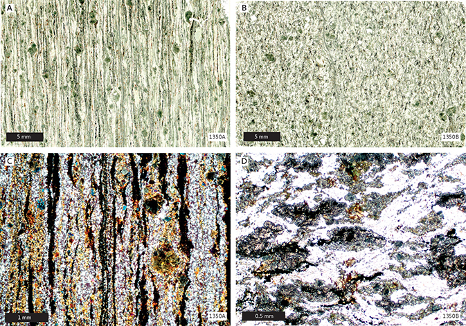
Fig. 76 A strongly deformed dyke where lineation is much stronger than foliation. A (1 nicol), C: sample 1350A, cut parallel to the lineation. B (1 nicol), D: sample 1350B, cut perpendicular to the lineation. In C (x nicols), trails of fine-grained garnet (black) and recrystallised plagioclase outline the fabric. Larger brownish grains survive igneous clinopyroxenes. D (1 nicol), cut across the linear structure, shows reddish garnet, ilmenite, a few green amphiboles and some recrystallised clinopyroxenes. South shore of central Itillip Ilua.
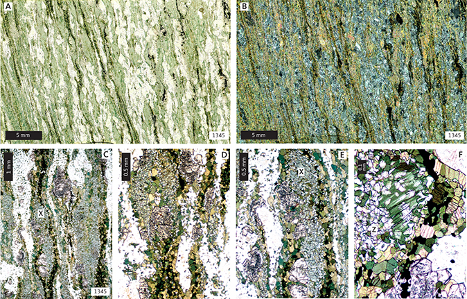
Fig. 77 A strongly deformed dyke. Sections cut perpendicular to the foliation. A: 1 nicol. B: X nicols. C–F: 1 nicol. ‘X’ in panels C, E: relic igneous clinopyroxene. ‘Z’ in panel F: recrystallised clinopyroxene. Sample 1345. South shore of central Itillip Ilua.
Two examples of strongly deformed dykes are shown in Fig. 78. These thin sections are cut both parallel to the strongest directional fabric and at right angles to this. It appears that the linear fabric is much more strongly developed than the planar fabric. It is also worth noting that, even in the most strongly deformed rocks in Figs 77 and 78, the original igneous sub-ophitic microstructure is still discernible.
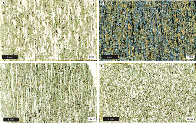
Fig. 78 A strongly deformed dyke. A: sample 1300, 1 nicol. B: sample 1300, X nicols. In B, garnets stand out as black. C: sample 1321A, 1 nicol, cut perpendicular to apparent foliation. D: 1321B, 1 nicol, cut perpendicular to lineation and showing the linear nature of the fabric. Both samples north shore of central Itillip Ilua.
6.1.2.2 Complete granoblastesis, strong deformation
A combination of strong deformation and the disappearance of all igneous minerals effectively erases the original igneous microstructure. A transitional case is illustrated in Fig. 79, where all minerals are metamorphic, but the distribution of plagioclase and amphibole is suggestive of an igneous origin. This is particularly evident in the thin section that is orientated perpendicular to the rock’s linear fabric (Fig. 79A, B).
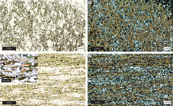
Fig. 79 A completely recrystallised dyke. A, C: sample 1141A, 1 nicol, perpendicular to lineation. B, D: sample 1141B, X nicols, parallel to lineation. Outer Saqqap Kangerluarsua.
With further growth of metamorphic minerals, the relict igneous mineral distribution is eventually lost. Figure 80 shows this final development of a granoblastic, metamorphic fabric. The deformed nature of these rocks is indicated by a strong crystallographically preferred orientation of amphiboles as shown by their pleochroism (Fig. 80C).
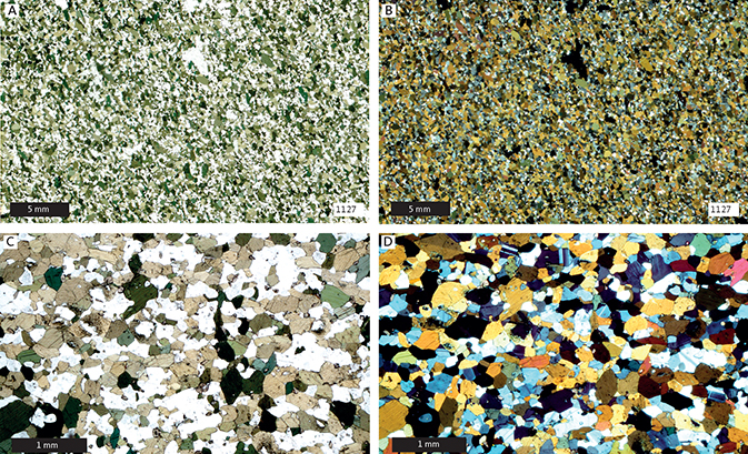
Fig. 80 Dyke completely converted into a metadyke, or amphibolite, (sample 1127). A, C: 1 nicol. B, D: X nicols. Planar fabric mainly outlined by amphibole pleochroism. Innermost Saqqap Kangerluarsua.
6.1.3 Conclusions regarding granoblastesis
Microstructurally, the transformation from sub-ophitic dykes into granoblastic amphibolites involves (1) recrystallisation of existing minerals, (2) growth of new mineral phases and (3) the simultaneous migration of material to produce a rock where mineral phases are more or less evenly distributed or where these are concentrated in bands of light and dark minerals.
The formation of a banded microstructure in the metadykes clearly involves strong deformation (Fig. 78). Igneous laths of plagioclase are transformed into elongate aggregates of smaller granoblastic grains through dynamic recrystallisation. In response to the initial deformation, plagioclase laths develop new grains either marginally or along plagioclase–plagioclase grain contacts (Fig. 72). As deformation proceeds, these aggregates are stretched into extremely long trails that conform to the prevailing strain field. This observation bears a striking resemblance to structures found in mylonites.
6.2 Metamorphism of dykes and country rocks
How undeformed dykes from Maniitsoq to Itillip Ilua have been affected by metamorphic overprinting is covered in detail in Chapter 5. In parts of the Itillip Ilua region, and especially north of Qaqqatoqaq, these overprinting processes have run to completion and have resulted in dykes being converted into metadykes or essentially amphibolites.
Textural aspects of the transformation were covered in Section 6.1. In this Section, we describe the metamorphic effects of the Nagssuqtoqidian deformation on dykes and country rocks north of Itillip Ilua. Along the north shore of Saqqap Kangerluarsua and in Qeqertalik (Fig. 81), the effects of Nagssugtoqidian deformation on the country gneisses are relatively slight and are mainly expressed as the folding of earlier fabrics, around E–W subhorizontal axes (Section 3.2). The effects on the dykes appear more penetrative. In addition to being folded together with the gneiss fabrics, the dykes north of Saqqap Kangerluarsua are completely converted into metadykes or amphibolites without any traces of the original igneous mineralogy or microstructure. However, the dykes do not lose their identity as dykes and are clearly recognisable as former intrusive bodies. The changes in both dyke and country rock mineralogy, from Nuussuup Qulaa to Maligiaq, are summarised in Figs 82 and 83.
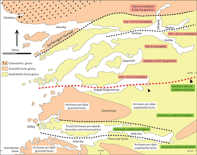
Fig. 81 Simplified geological map of the Itillip Ilua – Ikertooq region, summarising metamorphic grades and mineral assemblages within both metadykes and host gneisses. See also Fig. 84. Dashed red line in centre of map marks the approximate southern boundary of pervasive Nagssugtoqidian deformation and metamorphism. Consequently, Kangâmiut dykes north of this line are all converted to metadykes. South of the line partly deformed and metamorphosed dykes (margins or centres) occur, but these dykes are not completely deformed or metamorphosed. Cpx: clinopyroxene. Hbl: hornblende. Grt: garnet. Opx: orthopyroxene. Qtz-fsp: quartzo-feldspathic gneiss. Map based on fig. 2A in Korstgård et al. 2006.
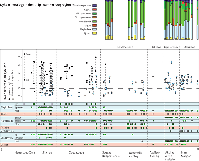
Fig. 82 Variations in dyke and metadyke mineralogy across the Itillip Ilua – Ikertooq region (location in Fig. 2). Upper right histograms show modal proportions of metamorphic minerals for metadyke samples north of Qaqqatoqaq. In the main diagram, An content in plagioclase (Rim to Core) in dykes (black dots) and metadykes (blue dots) is shown. Note systematic increase in An content in plagioclase in metadykes. Note also the change in colour of amphibole, appearance of orthopyroxene and metamorphic clinopyroxene in northernmost zones. Hbl: hornblende. Cpx: clinopyroxene. Grt: garnet. Opx: orthopyroxene. ign: igneous. met: metamorphic.
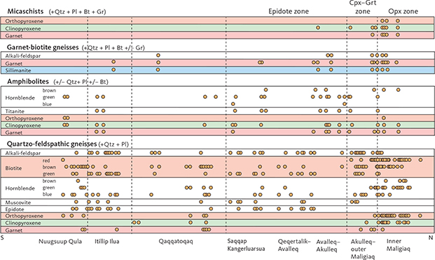
Fig. 83 Variations in country rock mineralogy across the Itillip Ilua – Ikertooq region (location in Fig. 2). There is a systematic northward change in colour of amphibole from blue-green to brown-green and in biotite from green-brown to red-brown for all rock types north of Saqqap Kangerluarsua. In quartzo-feldspathic gneisses orthopyroxene, clinopyroxene and garnet appear in northernmost zones, whereas epidote and muscovite disappear in these zones. Bt: biotite. Cpx: clinopyroxene. Gr: graphite. Grt: garnet. Opx: orthopyroxene. Pl: plagioclase. Qtz: quartz.
Based on the mineral assemblages of metamorphosed dykes, the area between Saqqap Kangerluarsua and Maligiaq can be divided into a number of metamorphic zones (Figs 81, 84).
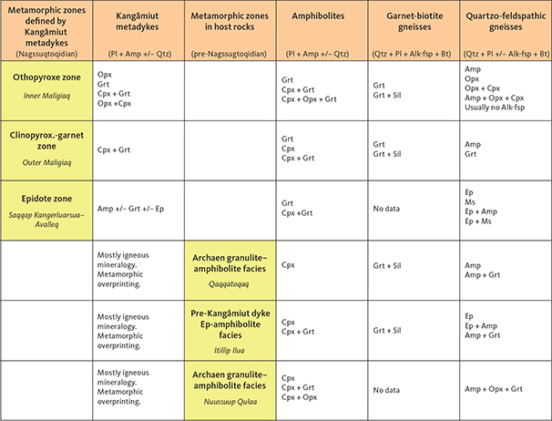
Fig. 84 Mineral parageneses across the Ikertooq region from south (bottom of diagram) to north (top of diagram; see also Fig. 81). The first two columns on the left are based on Kangâmiut dyke mineralogy, the four columns to the right are based on host-rock mineralogy. The three rows at the bottom of the diagram show pre-Nagssugtoqidian parageneses whereas the upper three rows show parageneses of Nagssugtoqidian age. Alk-fsp: alkaline feldspar. Amp: amphibole. Bt: biotite. Cpx: clinopyroxene. Ep: epidote. Grt: garnet. Opx: orthopyroxene. Pl: plagioclase. Qtz: quartz. Sil: sillimanite.
6.2.1 Epidote zone
The epidote zone extends from the southern shore of Saqqap Kangerluarsua to the south shore of Ikertooq and Akulleq (Fig. 81). The zone is characterised by the common occurrence of epidote in quartzo-feldspathic gneisses and locally in metadykes. Amphibole is the main ferro-magnesian mineral in metadykes, while garnet is an occasional additional phase. The original igneous clinopyroxene + plagioclase assemblage has been completely converted into a metamorphic amphibole + plagioclase ± garnet assemblage. These metadykes are proper amphibolites, consisting of about 60% amphibole, 30% plagioclase and 5% quartz (Fig. 82). They have a granoblastic microstructure that usually has a well-developed planar and linear fabric (Fig. 85), defined by a preferred orientation of elongated amphiboles. The amphiboles are blue-green, and plagioclases are typically oligoclases (Fig. 82). Biotite is a common minor constituent, and titanite and ilmenite may co-exist (Fig. 85) with titanite often rimming ilmenite. Compared to the almost completely metamorphosed dykes found locally on Qaqqatoqaq, it is surprising that garnet is virtually absent within the epidote-zone metadykes. It has not been possible to find microstructural evidence of any garnet-consuming reactions and it is possible that – due to subtle bulk compositional differences – garnet was never produced in these metadykes.
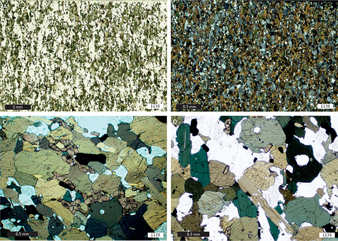
Fig. 85 Metadyke in low amphibolite facies. A, B: foliated granoblastic microstructure with a planar fabric. C: amphibole and titanite (dirty brown). D: amphibole and biotite. A, C, D: 1 nicol. B: X nicols. Sample 1138. North shore of inner Saqqap Kangerluarsua.
The typical mineral assemblage in the country gneisses is quartz + alkali feldspar + plagioclase + green-brown biotite + epidote. Other common minerals are blue-green amphibole and muscovite (Fig. 83). The mineral assemblages in the quartzo-feldspathic gneisses of this epidote zone represent a downgrading or retrogression of the mineral assemblages seen in the Archaean gneisses on Qaqqatoqaq. Amphibolites however, seem less affected, with clinopyroxene and garnet still being present.
Structurally the rocks in the epidote zone are characterised by intermediate (outcrop scale) to large-scale folding, around E–W-trending and subhorizontal axes, of both earlier Archaean fabrics and hosted metadykes. No new fabrics are associated with these folds. Further north, in Avalleq, the Nagssugtoqidian deformation becomes more intense.
6.2.2 Clinopyroxene–garnet zone
The disappearance of epidote and muscovite in the gneisses and an increased abundance of garnet in metadykes (Fig. 86) mark an increase in metamorphic grade in an area that encompasses the outer part of Avalleq and the southern part of Akulleq (Fig. 81).
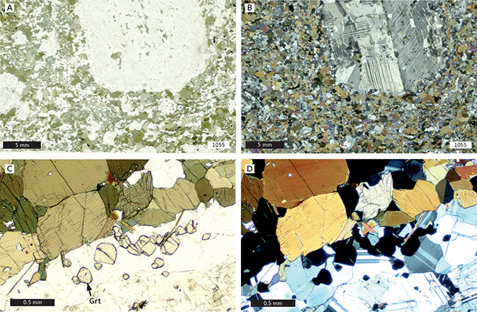
Fig. 86 Metadyke in amphibolite facies. A, B: large plagioclase porphyroblast in amphibolite facies metadyke. C, D: with small garnet grains in amphibolite facies metadyke. A, C: 1 nicol. B, D: X nicols. Sample 1055. Head of Avalleq. Grt: garnet.
In the area between the south shore of Ikertooq and halfway into Maligiaq (Fig. 81), clinopyroxene appears (Fig. 87) and commonly occurs together with garnet, as well as amphibole and plagioclase in metadykes. The most common assemblage in this zone is plagioclase + amphibole + clinopyroxene ± garnet (Fig. 88), whereas plagioclase + amphibole ± garnet is rare. Titanite may occur as an accessory phase but is partially replaced by ilmenite (Fig. 89). The colour of amphibole has changed from grass-green to brown-green and the anorthite content of plagioclase has increased to well over 30% (Fig. 82).
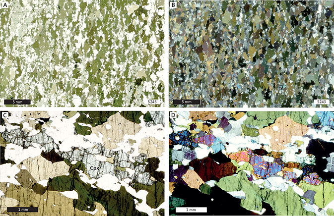
Fig. 87 Upper amphibolite facies metadyke. A (1 nicol), B (X nicols): good foliation with amphibole (dark green) and clinopyroxene (light green). C (1 nicol), D (X nicols): clinopyroxene in centre. Sample 5243. North shore of outer Akulleq.
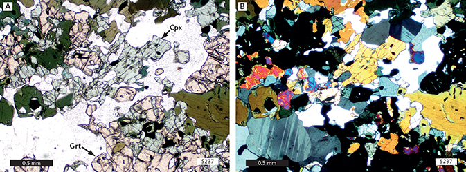
Fig. 88 Metadyke from clinopyroxene–garnet zone. A: (1 nicol) garnet (Grt; pink), clinopyroxene (Cpx; light green), and amphibole (dark green). B: is the same with X nicols. Sample 5257. North shore of inner Akulleq.
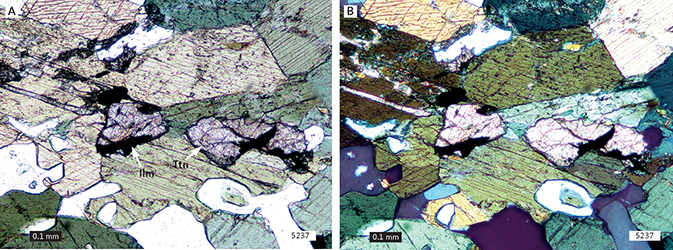
Fig. 89 Titanite (Ttn; centre of section) being replaced by ilmenite (Ilm). A: 1 nicol. B: X nicols. Sample 5237. North shore of inner Akulleq.
Epidote has disappeared from the host gneisses (Fig. 83) and only traces of muscovite are present. The typical assemblage in the host gneisses is quartz + alkali feldspar + plagioclase + brown biotite, together with occasional green amphibole, clinopyroxene and garnet.
6.2.3 Orthopyroxene zone
The appearance of orthopyroxene in both metadykes and gneisses marks the transition from amphibolite to granulite facies. The orthopyroxene zone extends from halfway into Maligiaq to the northernmost point mapped in Fig. 81 and is characterised by the occurrence of orthopyroxene in all rocks of suitable compositions. The most common assemblage in the metadykes is plagioclase + amphibole + orthopyroxene + clinopyroxene; less commonly plagioclase + amphibole + clinopyroxene + garnet (Fig. 90). A single metadolerite with the anhydrous assemblage plagioclase + orthopyroxene + clinopyroxene is also found (Fig. 91B). Titanite is no longer present, amphibole is typically brown, and the anorthite content of plagioclase has further increased to around 40% (Fig. 82).
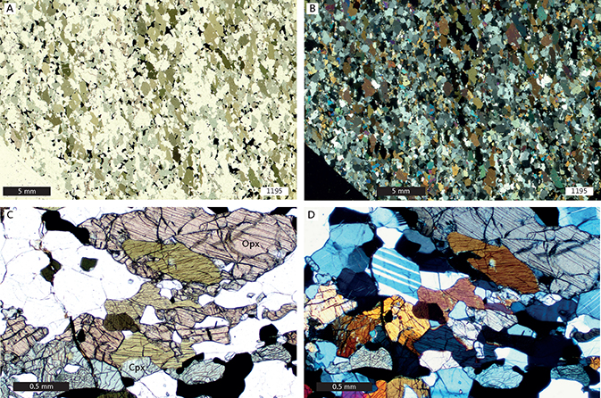
Fig. 90 Granulite facies metadyke showing orthopyroxene (Opx; pink), clinopyroxene (Cpx; light green), amphibole (green) and ilmenite (opaque). A, C: 1 nicol. B, D: X nicols. Sample 1195. Inner Maligiaq.
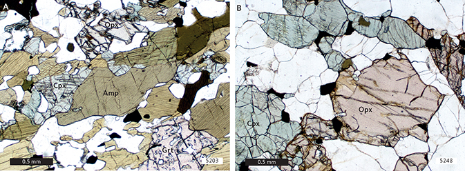
Fig. 91 Granulite facies metadyke. A: Coexisting orthopyroxene, clinopyroxene, amphibole, garnet and plagioclase. 1 nicol. Sample 5203. B: Coexisting orthopyroxene, clinopyroxene and plagioclase. 1 nicol. Sample 5248. Inner Maligiaq. Amp: amphibole. Cpx: clinopyroxene. Grt: garnet. Opx: orthopyroxene.
In quartzo-feldspathic gneisses, a typical mineral association is quartz + plagioclase + red-brown biotite + brown-green amphibole + orthopyroxene ± clinopyroxene (Fig. 83). The almost complete absence of alkali feldspar is puzzling, since it cannot be attributed to any alkali-feldspar-consuming reaction in the gneisses. It is associated with a significant drop in the potassium content of the gneisses that must be either a primary feature or connected with metasomatic or partial melting processes (discussed further in Chapter 7). The facies transition in Maligiaq is very sharp and takes place within a few hundred metres in both dykes and gneisses.
6.2.4 Summary of metamorphic mineral assemblages between Saqqap Kangerluarsua and Maligiaq
The progression of mineral assemblages during the metamorphism of basic rocks is typically illustrated by a series of ACF diagrams (where A = Al2O3 – K2O – Na2O, C = CaO, F = FeO(tot) + MgO + MnO, all molecular proportions). While most basic rocks are chemically complex and contain too many components to be accurately depicted in ACF space (e.g. Spear 1993), we find that the changes in mineral assemblages from Saqqap Kangerluarsua to Maligiaq can be displayed schematically in ACF diagrams. In Fig. 92, we display actual mineral and whole-rock compositions from the three zones defined previously (Sections 6.2.1–6.2.3). For the two northern zones, the lowest variance assemblage observed was chosen to represent the metamorphic conditions and mineral diversity. For the southernmost zone (Epidote zone) two different mineral assemblages are shown (samples 1132 and 1128). Note that due to limitations mentioned in previous sections, crossing tie-lines (e.g. plagioclase–orthopyroxene crossing garnet–clinopyroxene) does not necessarily mean that these mineral reactions took place (Spear 1993).
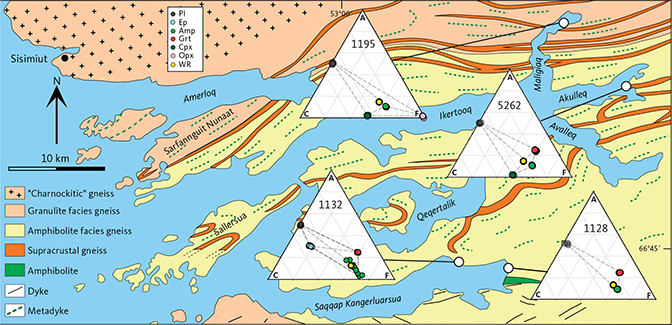
Fig. 92 Data from four representative dyke samples between Saqqap Kangerluarsua and Maligiaq. ACF diagrams include sample numbers and illustrate progressive changes in mineral assemblages from lower amphibolite to granulite facies. Mineral analyses for plagioclase, clinopyroxene, amphibole, garnet, and orthopyroxene are plotted under the assumption that all Fe is Fe2+, whereas all Fe in epidote (sample 1132) is assumed to be Fe3+. For consistency, whole-rock data are also plotted assuming all Fe to be Fe2+. In all mineral assemblages, quartz and a hydrous fluid phase are assumed present. A: (Al2O3 – K2O – Na2O). C: CaO. F: (FeO(tot) + MgO + MnO), all molecular proportions. Amp: amphibole. Cpx: clinopyroxene. Ep: epidote. Grt: garnet. Opx: orthopyroxene. Pl: plagioclase. WR: whole-rock data.
In the epidote zone, between Saqqap Kangerluarsua and Avalleq, mineral assemblages are plagioclase + amphibole ± garnet ± epidote. Generally, garnet occurs in more Fe-rich bulk compositions, whereas epidote is more common in Ca-richer rocks. In one sample, however (1132, shown in Fig. 92), all four phases are present. This marks the transition to lower amphibolite facies (e.g. Bucher & Frei 1994).
In the clinopyroxene–garnet zone, between Avalleq and Akulleq, all epidote has been consumed, and the typical assemblage is plagioclase + amphibole + garnet, with garnet becoming volumetrically more important than in the lower grade zone (no samples from this zone were analysed). Clinopyroxene appears between Avalleq and outer Maligiaq, and a common assemblage is now plagioclase + amphibole + clinopyroxene + garnet (represented by sample 5262 in Fig. 92). This assemblage is typical of upper amphibolite facies.
Granulite facies conditions are reached in the orthopyroxene zone, in the inner part of Maligiaq. The mineral assemblages are the same as in the clinopyroxene–garnet zone, except that orthopyroxene is now stable in rocks of suitable composition. Orthopyroxene-bearing and orthopyroxene-free assemblages can coexist at the same temperature, if the proportion of water in the attending fluid phase varies from low to high, respectively. In this zone, the general assemblages found are plagioclase + amphibole + clinopyroxene ± orthopyroxene ± garnet (all phases present in sample 1195 in Fig. 92). Figure 82 shows the appearance and modal increase in both orthopyroxene and clinopyroxene in the orthopyroxene zone.
Throughout this sequence, amphiboles are increasingly consumed through dehydration reactions (decreasing modal contents; Figs 50, 82), and their compositions are continuously changing (migrating from close to the ‘C–F’ line towards the ‘A’ apex in ACF diagrams; Fig. 92). In addition to pressure and temperature, the nature and progress of these amphibole-consuming reactions is a function of bulk-rock composition and fluid composition. However, in the present sequence of rocks, the ultimate disappearance of amphiboles is never reached. Metamorphic plagioclase similarly changes composition as a result of the reactions that characterise the progression from Saqqap Kangerluarsua to Maligiaq. While the ACF projections in Fig. 92 do not show compositional variations of plagioclase, Fig. 82 shows how the anorthite content of plagioclase increases from Itillip Ilua to Maligiaq.
6.3 Types of facies transitions in the Itillip Ilua – Ikertooq region
6.3.1 Facies transitions
Within the Itillip Ilua – Ikertooq region, three types of facies transitions or boundaries are recognised, based on whether accompanying metamorphism was prograde or retrograde as well as on the intensity of the accompanying deformation (Korstgård 1979b). The first two pre-date Kangâmiut dyke emplacement, whereas the last one affects the dykes as well as their host rocks.
- The amphibolite-granulite facies transition in the Archaean areas of Qaqqatoqaq and Nuussuup Qulaa (Fig. 93) is prograde and static, in the sense that the boundary was not established as a result of a deformational event but reflects static equilibration of mineral assemblages to the conditions that prevailed when the rocks were at their deepest crustal level. During later uplift, the rocks escaped any significant metamorphic changes (retrogression) due to absence of deformation.
- The granulite to low amphibolite facies and amphibolite to low amphibolite facies transitions along Itillip Ilua are retrograde and dynamic, in the sense that these were established as a direct consequence of the shearing along the Itilleq shear zone. Mineral assemblages in the shear zone equilibrated to the metamorphic conditions at a higher crustal level, while the shearing facilitated the retrogression.
- The amphibolite–granulite facies transition in Maligiaq (Fig. 93) is both prograde and dynamic. It could be considered a displaced prograde and static transition that has been thrusted into a subvertical position. Its position at the present level of erosion is clearly a result of deformation. The nature of thrusting is that rocks from a deeper crustal level are brought up on the hanging-wall side and a greater load is placed on rocks on the foot-wall side. Due to this, regions bounding a ductile overthrusting shear zone will suffer metamorphic and deformational effects not experienced by regions adjacent to ductile transcurrent shear zones, which are largely unaffected by the shearing.
6.3.2 Metamorphic boundaries and magnetic anomalies
A magnetic anomaly map for the Ikertooq region shows a remarkable correlation with metamorphic boundaries (Fig. 94; Korstgård et al. 2006). Thus, within the Archaean granulite facies areas, just north and south of Itillip Ilua (‘A’ in Fig. 94), strong magnetisations are attributed to a high content of magnetite, formed through the breakdown of hydrous mafic minerals (biotite, amphibole) during the transition from amphibolite facies to granulite facies. The gradual increase in magnetic intensity, from B to C to A in Fig. 94, even conforms to this gradual prograde facies transition.
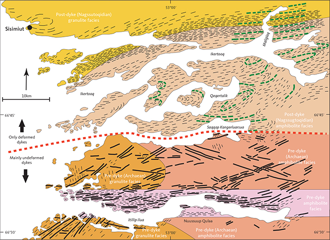
Fig. 93 Simplified map of the Itillip Ilua – Ikertooq area, showing the distribution of relative pre- versus post-dyke ages of the main metamorphic facies, south and north of a boundary (red dashed line) through Saqqap Kangerluarsua. Thick black lines: undeformed or only partly deformed dykes. Thick dashed green lines: deformed dykes (only a few shown). Thin black dashed lines: planar structures in host rocks. The dashed red line marks the southern limit of completely deformed and metamorphosed Kangâmiut dykes.
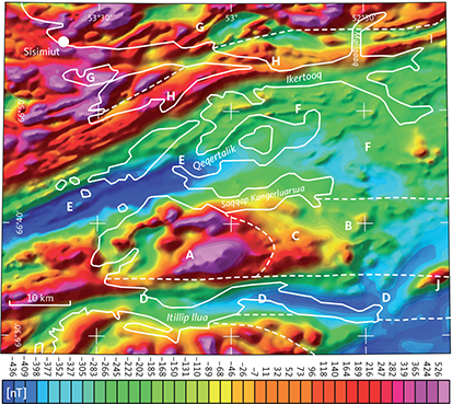
Fig. 94 Magnetic anomaly map for the Itillip Ilua – Ikertooq area (modified from Korstgård et al. 2006) showing the strong correlation between metamorphic boundaries and the magnetic signatures. A–J: magnetic anomaly centres described in Korstgård et al. 2006. The dashed white lines correspond to the metamorphic facies boundaries in Fig. 93. Within the Archaean granulite facies areas, just north and south of Itillip Ilua (A), strong magnetisations are attributed to a high content of magnetite, formed through the breakdown of hydrous mafic minerals (biotite, amphibole) during the transition from amphibolite to granulite facies. The gradual increase in magnetic intensity, from B to C to A, even conforms to this gradual prograde facies transition. The E–W-trending low magnetic anomaly, coincident with the Itilleq shear zone (D), is most likely caused by breakdown of magnetic minerals during metamorphic retrogression, from granulite facies or upper amphibolite facies (A, B, C) to epidote amphibolite facies in the shear zone (D). The post-dyke lower amphibolite facies rocks along Qeqertalik (E and F) also display low magnetic anomalies, whereas the upper amphibolite to granulite facies rocks along the Ikertooq shear zone and northwards display high magnetic anomalies (H and G). Isolated high intensity anomalies can also locally be correlated with distinct lithologies or intrusions (e.g. the anorthosite complex at J).
The E–W-trending low magnetic anomaly, coincident with the Itilleq shear zone (‘D’ in Fig. 94), is most likely caused by breakdown of magnetic minerals during metamorphic retrogression, from granulite facies or upper amphibolite facies (‘A’, ‘C’ and ‘B’ in Fig. 94) to epidote amphibolite facies in the shear zone (‘D’ in Fig. 94).
The post-dyke lower amphibolite facies rocks along Qeqertalik (‘E’ and ‘F’ in Fig. 94) also display low magnetic anomalies, whereas the upper amphibolite to granulite facies rocks along the Ikertooq shear zone and north display high magnetic anomalies (‘H’ and ‘G’ in Fig. 94).
Isolated high intensity anomalies can also locally be correlated with distinct lithologies or intrusions (e.g. the anorthosite complex at ‘J’ in Fig. 94). The presence or absence of Kangâmiut dykes is not reflected in the aeromagnetic data. The observed correlation between metamorphic facies, deformation and magnetisation can be extended to other areas of the Southern Nagssugtoqidian orogen (Fig. 95).
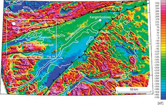
Fig. 95 Total intensity magnetic field anomaly map across the southern Nagssugtoqidian orogen. The southern foreland of the Nagssugtoqidian Orogen from the coast to the Greenland ice sheet is shown along with the location of the Itillip Ilua – Ikertooq region. White frame: locates Fig. 94. ?: location of thrust uncertain. (modified from Korstgård et al. 2006).
7 Chemical changes in dykes and country rocks from Nagssugtoqidian deformation and metamorphism
The Kangâmiut dyke swarm was variably affected by metamorphism and deformation from Area 01 to Area 11 (see Chapters 5 and 6), but as shown in Section 4.2, the dominant compositional variations observed were those associated with magmatic differentiation processes – mainly fractional crystallisation and minor crustal contamination (Mayborn et al. 2008) – with expected differences between chilled margins and later, more leucocratic interiors. There is no evidence that the metamorphic and structural overprints on the dykes in Areas 01 to 07 significantly altered their bulk composition. However, some data are suggestive of potential element mobility in areas farther north. To investigate the nature and magnitude of any bulk chemical changes that the dykes and their country rocks may have experienced during amphibolite and granulite facies metamorphism in the northernmost areas, we will look at more mobile large-ion lithophile (LIL) elements identified earlier, and major and trace elements traditionally associated with increased mobility during medium to high-grade metamorphism (e.g. Bridgwater 1979, Rollinson 1993). The purpose of identifying and quantifying any compositional variations due to deformation and metamorphism is to ensure that observed metamorphic mineral assemblages reflect metamorphic conditions and not a combination of metamorphism and bulk compositional changes.
7.1 Kangâmiut dykes
Figure 96 displays the south-to-north (Area 01 to Area 11, see Fig. 46) compositional variations for selected elements of interest. To minimise any effects of fractionation, we have normalised each of the potentially mobile elements to an incompatible element (Zr). The two most mobile LIL elements (Rb, K) show minimal or non-systematic variations between Areas 01 and 08, a slight increase from Area 08 to 09 and then a marked decrease into Areas 10 and 11. Both K and Rb decrease from Area 09 to 11, however, Rb decreases more (cf. Fig. 56A), so K2O/Rb increases. Other LIL elements (Ba, Sr, Eu) do not show any significant variation (shown in Fig. 56A). Pb and U both decrease from Area 09 to 11, in accordance with behaviour typically observed during regional amphibolite and granulite facies metamorphism (e.g. Bridgwater 1979). Both Sm and Nd display similar, albeit muted, trends (Fig. 56A).
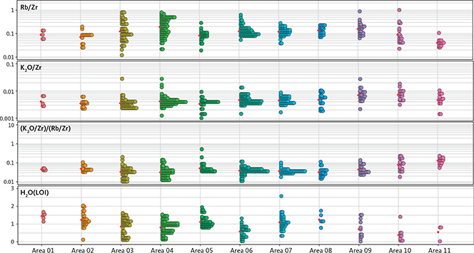
Fig. 96 Variations in dyke chemistry from south (Area 01, left) to north (Area 11, right) for those elements that display significant changes along the transect. To minimise the effect of fractionation, K2O and Rb have been normalised against an immobile element, Zr (ppm). Each coloured circle represents an analysis. Size of bins along y-axis: 1/30 of entire data range. The red diamonds show the mean value within each area. Rb decreases in Areas 10 and 11, whereas K2O only shows a moderate decrease, so the ratio between these elements shows a significant increase in the northernmost areas. H2O (LOI: Loss on ignition, in wt%) also shows lower values in Areas 10 and 11, in accordance with dehydration reactions taking place from amphibolite to granulite facies.
The ‘pseudo’-trends seen in the MgO vs K2O plot (Fig. 53) are, in light of the above, interpreted to represent normal variations to be expected among samples taken from margins and centres and from the leucocratic patches that are found in some dykes.
The K and Rb patterns in Areas 08 to 11 are best explained by the gradual breakdown of biotites and amphiboles with increasing metamorphic grade. The incompatible elements K and Rb are preferentially partitioned into the aqueous phase generated during breakdown of the hydrous minerals. Thus the granulite facies dykes are gradually depleted of these elements. The gradual breakdown was also demonstrated in Fig. 50, where a northwards volumetric decrease in hydrous minerals was evident.
The decrease in the volume of hydrous minerals is also shown by the overall decrease in analysed H2O (by loss on ignition; LOI). In Fig. 96, the range of H2O (LOI) is shown for all areas, and the decrease in Areas 09–11 relative to the remainder is clear.
Within individual dykes south of Area 09, there are similarly no signs of preferential LIL element mobility between margins and centres. Figure 97 shows available LIL data (K, Rb) from samples taken from margins to centres of dykes from Areas 02 to 08. To minimise the effect of fractionation, each element has been normalised to Zr. In this diagram, each block represents data collected from margins (left) to centres (right) of individual dykes. We see that K2O tracks Rb consistently, with Rb showing larger variations.

Fig. 97 Mobility of available LIL elements from margin to centre in individual Kangâmiut dykes in Areas 02 to 08. Data from H: Hansen (1989). W: Windley (1970). B: Bridgwater (unpublished data). M: Mayborn (2000). K: Korstgård (1980). Each block of data represents a single dyke sampled from margin (left) to centre (right). Most dykes show normalised K2O (green) tracking Rb (red) with no systematic changes. Consequently there are no signs of K2O:Rb increasing anywhere in the dyke in contrast to that observed in the higher-grade metamorphic zones (Area 10 and 11). K2O in wt%, Rb and Zr in ppm. Dyke orientation (thick black lines) and thickness data (in m) are shown where available.
7.2 Quartzo-feldspathic gneisses, amphibolites and supracrustal rocks
Data from the host rocks of the dykes, including tonalitic to granodioritic gneisses, amphibolites and various rocks of supracrustal origin, were collected in Areas 07–11 with the aim of characterising these lithologies and assessing any compositional changes associated with the increasing metamorphic grade (Korstgård 1980). In Section 7.1, we documented the chemical changes associated with element mobility driven by high-grade metamorphism in the Kangâmiut dykes. Here we will briefly see if similar changes are recorded by the host rocks.
The only elements that show a systematic and significant variation from Areas 07 to 11 are K and Rb (Fig. 98). Similar to the other element mobility plots, we have normalised the data to an incompatible element (Zr). The gneisses show K2O and Rb decreasing from Area 09 to 11, and since the Rb decrease is comparatively larger, K2O/Rb increases. This was the same trend observed in the Kangâmiut dykes, hosted by these gneisses. Similar trends may be hinted at by the amphibolites (one sample) and supracrustal gneisses (two samples), but the limited number of samples in these units from Area 11 precludes a definitive determination.
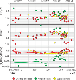
Fig. 98 Variations in K2O and Rb in rocks hosting Kangâmiut dykes from Areas 07 to 11. Data from quartzo-feldspathic gneisses, amphibolites and rocks of supracrustal origin are projected on to a c. 60 km long NNE–SSW-trending line from Maligiaq (right) to Itillip Ilua (left; see Fig. 2 for location of projection line; each unit along x-axis is c. 50 m). K2O and Rb are normalised against an immobile element, Zr. All lithologies show unsystematic and quite scattered variations in Areas 07 and 08. From Area 09 to 11, quartzo-feldspathic gneisses show a decrease in both K2O and Rb, however since the Rb decrease is larger, the resultant K2O:Rb increases dramatically in Area 11. Amphibolites and supracrustal gneisses show vaguely similar trends but those are based on relatively few samples. The smooth trend lines are calculated with the locally weighted least squares regression method. K2O in wt%, Rb and Zr in ppm.
8 Assessment of metamorphic conditions from observed mineral reactions and equilibria
Establishing the pressure and temperature conditions that the Kangâmiut dykes have experienced can provide useful constraints for reconstructing their tectonic history. Although numerous approaches are available for geothermobarometric calculations, a common underlying assumption for all is that thermodynamic equilibrium has been achieved among the mineral phases of interest. It is clear, however, from the evidence presented in previous Chapters, that the recrystallisation history for these rocks has been complex and episodic. Preservation of compositional zoning, symplectites, mineral overgrowths and reaction rims attest to localised compositional domains. Additionally, deformation may result in the juxtapositioning of minerals that had not thermodynamically equilibrated. Consequently, although the following discussion presents the quantitative results from rigorously applied geothermobarometric calculations, subjective decisions played a role in selecting which samples would be used and how results are interpreted. These choices are discussed next.
Although current approaches for calculating pseudosections (e.g. Forshaw et al. 2018) are powerful tools for establishing P–T conditions for metamorphic rocks, these also rely on the assumption that thermodynamic equilibrium has been achieved for the selected bulk-rock composition used in the calculation. From our discussions of mineralogy and textures, it is obvious that equilibrium is not satisfied for many of the samples that we have data for. Therefore, although we have pursued developments in such analyses (J. Forshaw, personal communication 2021), the results, as expected, are inconsistent with the microanalytical results we have obtained and are not shown here.
8.1 Geothermometry
8.1.1 Methodology
A suite of geothermometers was used for samples with appropriate mineralogies (Table 2). Clinopyroxene–orthopyroxene Brey et al. (1990) and clinopyroxene–garnet (Ellis & Green 1979) temperatures were often consistent with those derived from other geothermometers. However, these geothermometers were relevant for only a few samples, which made the amphibole–plagioclase (Blundy & Holland 1990) and Ti-in-amphibole (Liao et al. 2021) formulations more useful. In addition, separating remnant igneous pyroxene compositions from metamorphic compositions was not always possible. Therefore, in the following discussion we focus on results from the two amphibole-dependent formulations. In those instances where garnet and clinopyroxene were in contact, we used the Ellis & Green (1979) method to calculate temperatures, which generally provided results similar to those obtained from the Blundy & Holland (1990) and Liao et al. (2021; Table 3) formulations.
| Mineral assemblage | Parameter | Number of samples | Reference |
| Clinopyroxene–Orthopyroxene | T | 12 | Brey et al. (1990) |
| Clinopyroxene–Garnet | T | 20 | Ellis & Green (1979) |
| Amphibole–Plagioclase | T | 53 | Blundy & Holland (1990) |
| Ti in Ca-Amphibole | T | 53 | Liao et al. (2021) |
| Garnet–Orthopyroxene | P | 9 | Brey et al. (1990) |
| Amphibole–Garnet | P | 38 | Kohn & Spear (1990) |
| Sample no. | UTM E | UTM N | Amp–Pl | Amp–Pl | Amp–Pl | Amp–Pl | Ti-in-Amp | Ti-in-Amp | Ti-in-Amp | Ti-in-Amp | Ti-in-Amp | Grt–Opx | Cpx–Opx | Grt–Cpx | Amp–Grt |
| T: B&H P: 8 kbar (ave.) | T: B&H P: 8 kbar (low) | T: B&H P: 8 kbar (med.) | T: B&H P: 8 kbar (high) | T: L (ave.) | T: L (SD) | T: L P: B&H (low T) | T: L P: B&H (med. T) | T: L P: B&H (high T) | P: B, K&N | T: B, K&N | T: E&G | T: L P: K&S | |||
| (°C) | (°C) | (°C) | (°C) | (°C) | (°C) | (kbar) | (kbar) | (kbar) | (kbar) | (°C) | (°C) | (kbar) | |||
| 1011 | 411255 | 7404767 | 771 | 758 | 731 | 16 | 9.7 | ||||||||
| 1040 | 438047 | 7414090 | 706 | 695 | 749 | 679 | 27 | 9.0 | 12.4 | ||||||
| 1087 | 421068 | 7399136 | 768 | 756 | 655 | 12 | 14.3 | 5.15 | |||||||
| 1095 | 424617 | 7399104 | 728 | 628 | 722 | 738 | 56 | 6.8 | 646 | 9.30 | |||||
| 1106 | 422068 | 7400290 | 738 | 736 | 784 | 3 | 5.0 | 9.50 | |||||||
| 1116 | 422068 | 7400290 | 737 | 728 | 697 | 21 | 10.0 | ||||||||
| 1128 | 429611 | 7402547 | 737 | 741 | 808 | 16 | 3.7 | 11.36 | |||||||
| 1132 | 429460 | 7403180 | 743 | 655 | 726 | 849 | 748 | 19 | 6.5 | 12.5 | 7.11 | ||||
| 1145 | 432610 | 7425875 | 786 | 763 | 835 | 20 | 3.5 | 698 | 9.09 | ||||||
| 1195 | 436487 | 7428721 | 826 | 802 | 807 | 12 | 5.8 | 6.3 | 715 | ||||||
| 1285 | 427946 | 7390020 | 778 | 777 | 841 | 774 | 12 | 8.6 | 11.9 | 28 | 785 | 838 | 7.82 | ||
| 1286 | 427895 | 7390529 | 726 | 664 | 730 | 783 | 17 | 4.6 | |||||||
| 1294 | 418747 | 7391457 | 797 | 770 | 825 | 747 | 36 | 8.6 | 11.8 | 735 | 7.20 | ||||
| 1297 | 417338 | 7385655 | 762 | 755 | 789 | 7 | 5.9 | 12.65 | |||||||
| 1344 | 414256 | 7381330 | 764 | 561 | 753 | 870 | 719 | 10.1 | 16.2 | 23 | 768 | 630 | 7.27 | ||
| 1350 | 415815 | 7396749 | 712 | 710 | 843 | 21 | 650 | 11.50 | |||||||
| 5262 | 442982 | 7415142 | 816 | 782 | 815 | 728 | 15 | 11.7 | 12.1 | 736 | 6.95 | ||||
| 5268 | 448310 | 7414713 | 695 | 690 | 739 | 720 | 30 | 6.3 | 9.5 | ||||||
| 87777 | 405877 | 7282889 | 742 | 679 | 742 | 802 | 602 | 45 | 10.9 | 7.63 | |||||
| 158027 | 382875 | 7369451 | 875 | 835 | 786 | 18 | 10.8 | ||||||||
| 158035 | 392532 | 7303375 | 844 | 596 | 789 | 915 | 618 | 5 | 9.8 | 8.0 | 9.9 | 14 | 1080 | ||
| 414302 | 389792 | 7390193 | 764 | 763 | 825 | 822 | 33 | 4.2 | 8.2 | 20 | 780 | 9.16 | |||
| 414304 | 394475 | 7384980 | 907 | 910 | 827 | 33 | 12.3 | 875 | |||||||
| 414398 | 418894 | 7384771 | 803 | 674 | 774 | 766 | 40 | 8.5 | 788 | 7.41 | |||||
| 414399 | 418894 | 7384771 | 725 | 658 | 725 | 820 | 707 | 37 | 4.6 | 9.1 | 14.7 | 625 | 8.88 | ||
| 414404 | 415589 | 7385827 | 720 | 658 | 740 | 756 | 34 | 3.3 | 7.5 | 625 | 9.05 | ||||
| 414407 | 418894 | 7384771 | 742 | 741 | 764 | 14 | 6.5 | 734 | |||||||
| 414409 | 410711 | 7383886 | 767 | 618 | 763 | 775 | 34 | 8.0 | 647 | 8.16 | |||||
| 414410 | 410711 | 7383886 | 702 | 571 | 723 | 730 | 12 | 7.5 | 673 | 9.08 | |||||
| 414411 | 410711 | 7383886 | 782 | 743 | 808 | 35 | 4.4 | 11.90 | |||||||
| 414427 | 415589 | 7385827 | 699 | 645 | 795 | 18 | 10.37 | ||||||||
| 414429 | 415589 | 7385827 | 561 | 591 | 750 | 763 | 25 | 7.3 | 3 | 825 | 7.66 | ||||
| 414432 | 392438 | 7385112 | 788 | 758 | 780 | 41 | 6.6 | 733 | 13.21 | ||||||
| 414433 | 391089 | 7387335 | 778 | 769 | 846 | 809 | 13 | 5.5 | 10.1 | 735 | 7.35 | ||||
| 414434 | 426807 | 7413317 | 703 | 709 | 778 | 36 | 3.5 | 9.37 | |||||||
| 414438 | 413366 | 7397707 | 773 | 746 | 825 | 764 | 24 | 6.8 | 11.6 | 7 | 615 | 7.86 | |||
| 414442 | 393073 | 7380271 | 679 | 668 | 757 | 7.69 | |||||||||
| 414443 | 393073 | 7380271 | 813 | 644 | 739 | 829 | 763 | 44 | 6.5 | 11.9 | 7.69 | ||||
| 414445 | 393787 | 7379663 | 772 | 677 | 747 | 687 | 23 | 7.3 | 11.8 | 530 | 7.95 | ||||
| 414451 | 433189 | 7427186 | 794 | 788 | 830 | 853 | 18 | 4.5 | 6.7 | 959 | 9.20 | ||||
| 414476 | 435369 | 7428618 | 778 | 765 | 828 | 825 | 9 | 4.3 | 8.2 | 31 | 714 | 722 | 8.44 | ||
| 414479 | 432621 | 7427568 | 720 | 609 | 730 | 764 | 56 | 2.7 | 5.8 | 22 | 743 | 586 | |||
| 430267 | 399057 | 7294061 | 733 | 623 | 766 | 804 | 816 | 27 | 5.1 | 7.2 | 848 | ||||
| 430274 | 399057 | 7294061 | 769 | 603 | 784 | 881 | 596 | 37 | 801 | ||||||
| 430275 | 399057 | 7294061 | 838 | 638 | 762 | 912 | 733 | 9.7 | 17.5 | 13 | 810 | 7.63 | |||
| 430285 | 399057 | 7294061 | 794 | 769 | 830 | 611 | 13.55 | ||||||||
| 430288 | 385957 | 7314303 | 772 | 575 | 760 | 869 | 738 | 46 | 9.3 | 15.3 | |||||
| 430289 | 385957 | 7314303 | 957 | 735 | 953 | 33 | |||||||||
| 430290 | 385957 | 7314303 | 744 | 743 | 575 | 18.6 | 13.09 | ||||||||
| 430294 | 385957 | 7314303 | 739 | 647 | 747 | 608 | 38 | 16.8 | 10.49 | ||||||
| 430295 | 385957 | 7314303 | 774 | 693 | 727 | 595 | 13.40 | ||||||||
| 430303 | 392360 | 7323943 | 817 | 604 | 853 | 797 | 80 | 11.1 | 7.19 | ||||||
| Abbreviations: Amp: amphibole. Cpx: clinopyroxene. Ep: epidote. Grt: garnet. Opx: orthopyroxene. Pl: plagioclase. Ti: titanium. UTM: Universal Transverse Mercator coordinates. Calibrations used: B&H: Blundy & Holland (1990). L: Liao et al. (2021). E&G: Ellis & Green (1979). B, K&N: Brey et al. (1990). K&S: Kohn & Spear (1990). | |||||||||||||||
The Ti-in-amphibole geothermometer (TiAT; Liao et al. 2021) is calibrated for Ca-bearing amphiboles and is pressure-independent. It relies solely on the Ti content in the tetrahedral coordination of amphiboles. As such, it is easy to use. However, because a range of amphibole compositions can form under different temperature and pressure conditions, not all amphibole analyses from a given sample can be used to establish temperature conditions. As a result, analyses from the 53 samples used for this calculation were screened to assure that they met the compositional restrictions defined by Liao et al. (2021). The amphibole-plagioclase geothermometer (APT) of Blundy & Holland (1990) is based on cation abundances in an amphibole’s A and T1 sites and therefore depend on appropriate site occupancy assignments. The 2020 updated spreadsheet by Locock (2014) was used to assign cation site occupancies in the analysed amphiboles. The computed temperature is also dependent upon the anorthite content of coexisting plagioclase. Given the complex history of these rocks and the significant degree of igneous compositional zoning within these plagioclases, it is obviously problematic to identify the appropriate amphibole and plagioclase composition to use in these calculations. Adding to this complexity is the fact that the derived geothermometer is pressure dependent. We have therefore chosen to calculate temperatures at 8 kbar (kilobar) from randomly paired plagioclase and amphibole analyses in each sample and identified temperature clusters within these results. These clusters consistently ranged from approximately 550°C to 700°C (“low” group in Table 3), 700°C to 800°C (“med.” group in Table 3) or were greater than 800°C (“high” group in Table 3). Then, to avoid any uncertainties relating to pressure dependencies, we averaged TiAT temperatures for the amphiboles inside each data cluster and used that temperature for our pressure calculations described below. This approach generally provided broadly consistent results for geographically neighbouring samples, as well as allowed for a screening of compositional outliers.
8.1.2 Results
The computed temperatures range from 550°C to c. 900°C (Table 3). Temperatures greater than 850°C are most commonly associated with samples that retain igneous textures. We interpret these samples to reflect partial re-equilibration of a remnant igneous mineralogy. Lower temperatures are commonly associated with clear textural evidence of metamorphic recrystallisation, as discussed earlier (Chapter 5). The regional pattern of temperatures is shown in Fig. 99. While this pattern is still complex, there are several features that stand out. In the vicinity of the Maligiaq, where the Ikertooq shear zone is well-defined, samples north of and inside this shear zone consistently preserve temperatures that exceed 800°C. Immediately south of that shear zone, temperatures are consistently lower; commonly reaching values in the range of 700°C to 770°C. These results are consistent with an upper amphibolite facies – granulite facies boundary that marks a transition from a lower grade footwall block and into an over-thrusted higher grade hanging wall block, as described in Chapter 6. Samples scattered throughout the central and southern areas record temperatures between 550°C and 700°C. The boundary north of which temperatures are consistently above 700°C is marked in Fig. 99. These lower temperatures may record late-stage retrogressions.
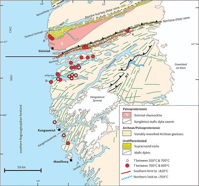
Fig. 99 Distribution of samples for which temperature calculations are available (see Table 3). In the legend, T is calculated temperatures. White circles overlapping red circles indicate samples in which temperatures formed distinct clusters in both groups. The red line (dashed where data are insufficient to tightly constrain location) indicates the southern limit of temperatures that exceeded 820°C; the blue dashed line is the northern limit of samples with temperatures below 700°C. Data sources: D: Davidson (1979). K: preliminary results from Kriegsman et al. (1996). Other symbols and abbreviations in Fig. 1.
8.2 Geobaromometry
8.2.1 Methodology
Pressure was calculated using several different approaches. The amphibole–garnet geobarometer (AG P ) of Kohn & Spear (1990) was used when these two phases were present. The amphibole cation site occupancy used in this calculation was the same as the one used for AP T calculations. Garnet end member proportions for grossularite, pyrope, almandine and spessartine were determined using the stipulations by Kohn & Spear (1990). Temperatures used in the calculations were those derived in Section 8.1.2 (Table 3; Fig. 99). The garnet–orthopyroxene barometer of Brey et al. (1990) was also used, when these mineral pairs coexisted (Table 3). Finally, we used an approach that combines the Ti-in-amphibole temperature, following Liao et al. (2021), with pressure-dependent temperatures that were computed from coexisting amphiboles and plagioclases, as prescribed by Blundy & Holland (1990). In this approach, we determined the pressure that would give the same temperature as the Ti method by Liao et al. (2021). All results are listed in Table 3. Since the latter method gave results for most samples, it is these results that we used in mapping the pressure variability across the region (Fig. 100).
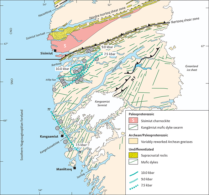
Fig. 100 Distribution of metamorphic pressures (in kbar) between Maniitsoq and Sisimiut. Grey circles: locations of samples used to constrain the isobars. ??: indicates uncertainty in the location and trend for the 7.5 kbar boundary. Other symbols and abbreviations in Fig. 1.
8.2.2 Results
The computed pressures range from c. 5 kbar to c. 13 kbar (Table 3). The higher and lower values in this broad range were based on amphibole–garnet pairs and could not be repeated with data from amphibole–plagioclase pairs from adjacent samples. We conclude that the amphiboles and garnets were likely not in thermodynamic equilibrium and thus do not represent actual P–T conditions experienced by samples. Pressure estimates based on coexisting amphibole and plagioclase showed much narrower intra- and inter-sample variations, and the isobars contoured in Fig. 100 were constructed from this perspective.
9 Discussion
In this Chapter, we briefly summarise the key findings and main conclusions and attempt to fit them into a coherent chronological and tectonic framework describing the Paleoproterozoic evolution of the southern Nagssugtoqidian orogen and its southern foreland. Key elements of this geodynamic evolution are also illustrated in Fig. 101.
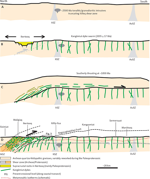
Fig. 101 Simplified cartoon illustrating the sequence of geological events described in the text for the study area between Maniitsoq and Ikertooq. A: Stable Archean crust intruded by tonalitic or granodioritic bodies at c. 2500 Ma. These units cut existing shear zones (ItSZ) of unknown, but likely Neoarchean age. IkSZ: Ikertooq shear zone. ItSZ: Itilleq shear zone. AuSZ: Aujassoq–Evighedsfjord shear zone. B: Localised crustal extension, deposition of sediments in the Ikertooq area and intrusion of the 2035 ± 17 Ma Kangâmiut dykes. C: Large-scale south-directed thrusting affects basement gneisses, sediments and dykes and causes widespread metamorphism in the footwall as far south as Maniitsoq. Metamorphic ages recorded by the dykes are around 1850 Ma. D: Strong deformation and metamorphism in the area between Itillip Ilua and Ikertooq with a northward-increasing gradient culminating in strongly sheared granulite facies rocks in Maligiaq thrust over amphibolite facies rocks. Most metamorphic ages are up to 100 Myr younger than those obtained farther south towards Maniitsoq. These ages may reflect a separate phase of tectonism or just the latest pulse in a protracted event starting with the thrusting in shown in panel C. PEL: the erosional level presently exposed along the coastal transect discussed here. Red box: approximate location of the red line shown in Fig. 93. Its relationship to the Nagssugtoqidian Front is not known nor is any implied. Geographic locations refer to locations along the coastal transect. Upper part of D, including the heavy black line, schematically represents observations farther east, closer to the Greenland ice sheet (slightly higher crustal levels due to the gentle eastward crustal tilt).
The tonalitic to granodioritic intrusions in Itillip Ilua represent the very earliest dated Paleoproterozoic event in the region. The c. 2500 Ma intrusives clearly truncate the penetrative fabrics in the Itilleq shear zone in the brittle domain, thus placing the formation of this shear zone into the (Neo-)Archaean era. Available radiometric ages indicate that the Itillip Ilua – Ikertooq area escaped major geological events for the next c. 450 My until the Kangâmiut dyke swarm intruded the area from Maniitsoq in the south to Sisimiut in the north.
As shown in Fig. 6 (Chapter 2), the available geochronological data clearly establish a Kangâmiut dyke emplacement age of c. 2035 Ma with a standard deviation of ±17 Ma. Given the regional extent of sampling, the total number of ages and the diverse techniques employed, this suite of dates confirms earlier arguments that this tectono-magmatic event marked the period of rifting that preceded Nagssugtoqidian orogeny.
However, the argument that the clusters of younger 40Ar–39Ar dates from Kangâmiut dykes (1857 ± 14 Ma and 1736 ± 20 Ma; Fig. 6) record slow cooling is not consistent with the overall metamorphic history of the orogen. Extensive dating on country rock gneisses, schists and metasediments has established two metamorphic episodes for the Nagssugtoqidian orogeny that cluster between c. 1850–1800 Ma and c. 1780–1720 Ma based on a range of techniques and isotopic systems (Taylor & Kalsbeek 1990; Kalsbeek & Nutman 1996; Whitehouse et al. 1998; Nutman et al. 1999; Connelly et al. 2000). These coincide, within their respective uncertainty envelopes, with the age data on metamorphic minerals from the Kangâmiut dykes. A single Sm–Nd age based on the metamorphic minerals garnet, amphibole and plagioclase (1840 Ma ± 80; Stecher et al. 1998) further confirm the presence and extent of the older metamorphic event.
Based on these observations, we conclude that the cumulative data support an emplacement age of the Kangâmiut dykes of 2035 ± 17 Ma. These data are consistent with the interpretation that the dykes experienced and preserved evidence for the same younger metamorphic events as other rocks within the Nagssugtoqidian orogen.
The younger metamorphic dates can also be identified locally in the enclosing host rocks (Fig. 5). It should be noted, however, that samples with Nagssugtoqidian metamorphic ages are quite sparse south of Itillip Ilua, hence further refinement of the age and extent of the metamorphic overprints as recorded by host gneisses is not possible farther south.
We envisage that the dykes were emplaced into an overall extensional setting or at least perpendicular to a minimum horizontal stress that could be overcome by the pressure of the ascending mafic magma bodies. Previous workers interpreted the apparent conjugate set of shear zones (sinistral NE–SW and dextral WNW–ESE zones) found locally in the host rocks and along the dykes as indicative of syn-tectonic dyke emplacement during overall NNW–SSE compression. In this model, these structures guided the geometry of the intruding dykes. Shears along dykes and in their marginal zones additionally suggest the presence of a NNW–SSE-orientated horizontal stress field during or after dyke emplacement or both. It is important to note that these ‘conjugate shears’ are only documented between Inussuttusup Tunua and Saqqap Kangerluarsua and locally along Kangerlussuaq.
We favour an alternative model involving the possibly oblique opening of a rift basin into which the Ikertooq supracrustals were deposited to take into account the 3–10% extension shown by the dyke swarm across the area (Escher et al. 1975). We interpret the shears along the margins and in the interiors of dykes between Inussuttusup Tunua and Saqqap Kangerluarsua to be a distal response to the contractional deformation (Nagssugtoqidian) responsible for the later deformation and metamorphism described in this study. This includes the high-grade deformation and metamorphism in the Ikertooq area and formation of the Ikertooq shear zone.
The orientation of the extensional stress field responsible for formation of the proposed rift basin(s) and for the orientation of the Kangâmiut dykes is poorly constrained at present. Its original geometry has largely been obliterated by subsequent Nagssugtoqidian orogenesis and more targeted work is clearly required to address this issue.
Available geochronological data indicate the presence of both Archean and Proterozoic sedimentary deposits in the Nagssugtoqidian orogen (e.g. Marker et al. 1999). The extent and volume of the supracrustal package in and along the Ikertooq shear zone suggest that these sediments were likely laid down in a regional-scale, elongate basin (the ‘Ikertooq basin’). Available age data shows the youngest detrital grains to be c. 2100 Ma (Nutman et al. 1999) and the observation that relatively few dykes intrude these supracrustal rocks suggests that the dykes were mainly emplaced in the extended margins of the crustal blocks bordering the basin. Additionally, it may also provide temporal constraints on the age of deposition, thus suggesting that the main phase of deposition may even post-date dyke emplacement.
More detailed discussion of the distribution, timing and significance of the supracrustal units in the Nagssugtoqidian Orogen is beyond the scope of the current paper.
Subsequent to emplacement, Kangâmiut dykes between Maniitsoq and Itillip Ilua suffered metamorphic overprints that range from thin amphibole rims on igneous clinopyroxenes to thoroughly recrystallised garnet-bearing metamorphic assemblages. The distribution of metamorphic overprints is very uneven, and all field observations and P–T calculations suggest that the isotherms and isobars of these overprints are gently undulating and largely sub-parallel with the present erosional surface (Fig. 101D). The extent to which the metamorphic reactions approached completion may also have been controlled locally by the limited availability of reactants, such as fluids.
Different structural and metamorphic overprints were demonstrated in dykes and their host rocks between Itillip Ilua and Maligiaq. In this area, the intensity of structural and metamorphic overprints increases gradually from south to north, culminating in granulite facies assemblages that were thrust southwards over amphibolite facies rocks in inner Maligiaq. In contrast to farther south, the isotherms between Itillip Ilua and Maligiaq are steeper and likely subparallel to the major thrust surfaces.
It is notable that most dykes with preserved discordances show intrusion features, indicative of emplacement into brittle country rocks, which agrees with petrological considerations indicating that the present exposure level was at depths corresponding to ≤3 kbar during dyke emplacement (Mayborn & Lesher 2006).
A mechanism by which these metamorphic overprints could have been generated has previously been proposed (Mengel et al. 1995, 1996; Mayborn & Lesher 2006) and involves the wholesale loading and burial of the southern foreland area between Ikertooq and Maniitsoq by large-scale south-directed overthrusting. This is supported by the calculated metamorphic pressures from minerals in the overprinting assemblage of 7.5 kbar in the southern areas around Maniitsoq and up to 10 kbar around Ikertooq (Fig. 100).
Available geochronological data from the dykes point toward two separate metamorphic events or pulses of a protracted period of foreland-directed thrusting. Most ages of interpreted metamorphic origin are c. 1880–1840 Ma between Maniitsoq and Itillip Ilua, whereas ages from north of Itillip Ilua to Ikertooq are generally younger by 100–120 Myr. A proposed explanation is that initial closure of the Ikertooq basin and subsequent collision involved large-scale, southerly directed overthrusting, and that a later phase of more limited extent mainly affected the Itillip Ilua – Ikertooq region, creating the Ikertooq shear zone and the dramatic contact between granulite- and amphibolite-facies rocks in Maligiaq. The younger age range notably correlates with structural and metamorphic events in the remainder of the Nagssugtoqidian orogen.
The observations summarised here are illustrated in Fig. 101. The figure does not reflect the varying orientation of the Kangâmiut dykes and only depicts schematically the difference in crustal levels exposed along the coast and towards the Greenland ice sheet. Similarly, the location of the Nagssugtoqidian Front (Fig. 101D) is not known in the coastal transect focused on here and may well be represented by multiple zones of strong deformation in contrast to the geometry observed east of Kangaamiut Sermiat (e.g. Fig 2).
The metamorphism recorded between Itillip Ilua and Maniitsoq (Fig. 101C) is interpreted to represent an earlier event, separate to the one that generated the metamorphic and structural signatures in the Itillip Ilua – Maligiaq area (Fig. 101D). It should be noted that additional geochronological studies could very well show that these two events represent separate pulses of one protracted episode of large-scale south-directed thrusting.
10 Concluding remarks
In this contribution, we have described some of the key features of the structural, metamorphic and compositional aspects of the Kangâmiut dykes between Maniitsoq and Ikertooq. The most pertinent of these include:
- compositional homogeneity of the Kangâmiut dykes across their mapped extent
- geochemical similarities to basalts in tectonic rift environments
- consistent intrusive ages around 2035 Ma (where data are available)
- uneven metamorphic overprints between Maniitsoq and Itillip Ilua
- a consistent structural and metamorphic gradient between Itillip Ilua and Ikertooq
- bimodal distribution of ages for metamorphic and structural overprints on the dykes
The thermobarometric results from the dykes imply that north of the Ikertooq shear zone, well preserved granulite-facies mineral assemblages developed at >800°C and about 10 kbar. South of the shear zone and inside the foreland towards Itillip Ilua, amphibolite facies mineral assemblages formed at approximately 700°C to 780°C and at pressures predominantly in the range of 6 kbar to 8 kbar. South of Itillip Ilua, data are sparser and display a slightly larger range than in the area between Ikertooq and Itillip Ilua.
Geochronological data discussed in this contribution suggest that the metamorphic overprints preserved in the area around Itillip Ilua and to the south were generated during a thermotectonic event around 1850–1800 Ma. A subsequent event at 1780–1720 Ma mainly affected the Ikertooq – Itillip Ilua area, likely overprinting the earlier event. The former event affected a much larger area, however the significance of this must await more dense sampling and further study.
Lastly, we remain in awe of the work by geologists in the early phases of investigations of the Precambrian in West Greenland. Their interpretations were based mainly on keen, but limited, field observations, however, the concepts they developed have largely stood the test of time.
Dedication
In 2023, our dear friend, colleague and co-author William E. Glassley suffered heart problems en route to Denmark, where we were to spend a week planning a highly anticipated field season in Greenland later in the summer. On arrival, Bill was transferred to Rigshospitalet in Copenhagen where he passed away the following day on 19 March. Bill’s involvement with Greenland geology started in the late 1970s and never ceased: Greenland became his destiny. He wrote about his fascination with Greenland in the book “A Wilder Time – notes from a geologist at the edge of the Greenland Ice”, which was published in 2018. It is a uniquely poetic narrative in the great American ‘Walden tradition’ of nature writing intertwined with science writing. Another friend of Bill’s, William Griffin, wrote in a review of the book: “Next time someone asks me why I am a geologist, I will just hand them this book”. We are lucky to have known Bill and fortunate to have worked with him. He is sadly missed.
Acknowledgements
JAK received support from the Danish Natural Science Research Council for field work in the Itillip Ilua – Ikertooq region in 1974–1975 where he participated in The Liverpool Precambrian Boundary Programme led by Juan Watterson. JAK and KS received support from the Geological Survey of Denmark and Greenland (GEUS) for field work in the Itillip Ilua – Ikertooq region in 2016. FCM was supported in 1994–1998 by the Danish Lithosphere Center Nagssugtoqidian project funded by the Danish National Research Foundation. WEG received support from the United States National Science Foundation in 1980, Aarhus University at various times in 2002–2015 and the Carlsberg Foundation in 2002. We wish to thank the reviewers for incisive and constructive comments and suggestions and acknowledge the GEUS Bulletin editors for their patience and feedback.
Additional information
Author contributions
JK, FCM, WEG: conceptualization, investigation, data curation, writing, review & editing. KS: structural model, review & editing.
Supplementary files
Two supplementary files are described in Appendix A and B. These files are available at https://doi.org/10.22008/FK2/YO2MIO. Supplementary file S1: geochemical data for Kangâmiut dykes. Supplementary file S2: mineral chemistry from Kangâmiut dykes.
References
Allaart, J.H. 1982: Geological map of Greenland 1:500 000, Sheet 2 Frederikshåb Isblink – Søndre Strømfjord. Copenhagen: Grønlands Geologiske Undersøgelse.
Allaart, J., & Jensen, S. 1979: Compilation of 1:500 000 reconnaissance mapping in the Precambrian of the Evighedsfjord – Søndre Strømfjord – Itivdleq region, southern West Greenland. Rapport Grønlands Geologiske Undersøgelse 95, 72–76. https://doi.org/10.34194/rapggu.v95.7651
Armbruster, T. et al. 2006: Recommended nomenclature of epidote-group minerals. European Journal of Mineralogy 18, 551–567. https://doi.org/10.1127/0935-1221/2006/0018-0551
Árting, U.E. 2004: A petrological study of basic dykes and sills of assumed Paleoproterozoic age in central West Greenland 193pp. MSc thesis. University of Copenhagen, Denmark. https://doi.org/10.13140/RG.2.1.4958.0966
Bak, J., Korstgård, J.A. & Sørensen, K. 1975a: A major shear zone within the Nagssugtoqidian of West Greenland. Tectonophysics 27, 191–209. https://doi.org/10.1016/0040-1951(75)90016-5
Bak, J., Sørensen, K., Grocott, J., Korstgård, J., Nash, D. & Watterson, J. 1975b: Tectonic implications of Precambrian shear belts in western Greenland. Nature 254, 566–569. https://doi.org/10.1038/254566a0
Blundy, J.D. & Holland, T.J.B. 1990: Calcic amphibole equilibria and a new amphibole-plagioclase geothermometer. Contributions to Mineralogy and Petrology 104, 208–224. https://doi.org/10.1007/BF00306444
Brey, G.P., Köhler, T. & Nickel, G. 1990: Geothermobarometry in four-phase lherzolites I. Experimental results from 10 to 60 kb. Journal of Petrology 31,1313–1352. https://doi.org/10.1093/petrology/31.6.1313
Bridgwater, D. 1979: Chemical and isotopic redistribution in zones of ductile deformation in a deeply eroded mobile belt. U.S. Geological Survey Open file report 79-1239, 505–512.
Bridgwater, D. & Gormsen, K. 1968: Precambrian rocks of the Angmagssalik area, East Greenland. Rapport Grønlands Geologiske Undersøgelse 15, 61–71. https://doi.org/10.34194/rapggu.v15.7180
Bridgwater, D., Mengel, F., Fryer, B., Wagner, P. & Hansen, S.C. 1995: Early Proterozoic mafic dykes in the North Atlantic and Baltic cratons: field setting and chemistry of distinctive dyke swarms. Geological Society, London, Special Publications 95(1), 193–210. https://doi.org/doi:10.1144/GSL.SP.1995.095.01.12
Bucher, K. & Frei, M. 1994: Petrogenesis of metamorphic rocks, 6th ed, 318 pp. Heidelberg: Springer-Verlag. https://doi.org/10.1007/978-3-662-03000-4
Cadman, A.C., Tarney, J., Bridgwater, D., Mengel, F., Whitehouse, M.J. & Windley, B.F. 2001: The petrogenesis of the Kangâmiut dyke swarm, W. Greenland. Precambrian Research 105, 183–203. https://doi.org/10.1016/S0301-9268(00)00111-X
Coney, P.J., Jones, D.L. & Monger, J.W.H. 1980: Cordilleran suspect terranes. J Nature 288, 329–333. https://doi.org/10.1038/288329a0
Connelly, J.N. & Mengel, F.C. 2000: Evolution of Archean components in the Paleoproterozoic Nagssugtoqidian orogen, West Greenland. Geological Society of America Bulletin 112, 747–763. https://doi.org/10.1130/0016-7606(2000)112%3C747:EOACIT%3E2.0.CO;2
Connelly, J.N., van Gool, J.A.M. & Mengel, F.C. 2000: Temporal evolution of a deeply eroded orogen: The Nagssugtoqidian Orogen, West Greenland. Canadian Journal of Earth Sciences 37, 1121–1142. https://doi.org/10.1139/e00-032
Connelly, J.N., Thrane, K., Kraweic, A.W. & Garde, A.A. 2006: Linking the Paleoproterozoic Nagssugtoqidian and Rinkian orogens through the Disko Bugt region of West Greenland. Journal of the Geological Society 163, 319–335. https://doi.org/10.1144/0016-764904-115
Davidson, L.M. 1978: Granulite facies rocks bordering the Ikertôq shear belt, central West Greenland. 190 pp. PhD thesis. The University of Liverpool, UK.
Davidson, L.M. 1979: Nagssugtoqidian granulite facies metamorphism in the Holsteinsborg region, West Greenland. Rapport Grønlands Geologiske Undersøgelse 89, 97–108. https://doi.org/10.34194/rapggu.v89.7570
Ellis, D.J. & Green, D.H. 1979: An experimental study of the effect of Ca upon garnet-clinopyroxene Fe-Mg exchange equilibria. Contributions to Mineralogy and Petrology 71, 13–22. https://doi.org/10.1007/BF00371878
Ellitsgaard-Rasmussen, K. & Mouritzen, M. 1954: An anorthosite occurrence from West Greenland. Meddelelser fra Dansk Geologisk Forening 12, 436–442.
Ermanovics, I. & Ryan, B. 1990: Early Proterozoic orogenic activity adjacent to the Hopedale block of southern Nain Province. Geoscience Canada 17, 293–297.
Ernst, R.E., Buchan, K.L. & Palmer, H.C. 1995: Giant dyke swarms, characteristics, distribution and geotectonic applications. In: Baer, G. & Heimann, A. (eds): Physics and chemistry of Dykes, 339 pp. Rotterdam: Balkema.
Escher, A.E. 1971: Geological map of Greenland, 1:500 000, Sheet 3, Søndre Strømfjord - Nûgssuaq. Copenhagen: Geological Survey of Greenland. https://doi.org/10.22008/FK2/PWIXBQ
Escher, A., Escher, J. & Watterson, J. 1975: The reorientation of the Kangâmiut dike swarm, West Greenland. Canadian Journal of Earth Sciences 12, 158–173. https://doi.org/10.1139/e75-016
Escher, A., Jack, S, & Watterson, J. 1976a: Tectonics of the North Atlantic Proterozoic dyke swarm. Philosophical Transactions of the Royal Society of London A280, 529–539. https://doi.org/10.1098/rsta.1976.0011
Escher, A., Sørensen, K. & Zeck, H.P. 1976b: Nagssugtoqidian mobile belt in West Greenland, In: Escher, A. & Watt W.S. (eds): Geology of Greenland, 77–95. Copenhagen: Geological Survey of Greenland. https://doi.org/10.22008/gpub/38209
Forshaw. J., Waters, D., Pattison, D., Palin, R. & Gopon, P. 2018: A comparison of observed and thermodynamically predicted phase equilibria and mineral compositions in mafic granulites. Journal of Metamorphic Geology 37, 53–179. https://doi.org/10.1111/jmg.12454
Fossen, H. 2016: Structural Geology. 524 pp. Cambridge University Press.
Friend, C.R.L. & Nutman, A.P. 2019: Tectono-stratigraphic terranes in Archaean gneiss complexes as evidence for plate tectonics: The Nuuk region, southern West Greenland. Gondwana Research 72, 213–237. https://doi.org/10.1016/j.gr.2019.03.004
Gardiner, N.J., Kirkland, C.L., Hollis, J., Szilas, K., Steenfelt, A., Yakymchuk, C. & Heide‑Jørgensen, H. 2019: Building Mesoarchaean crust upon Eoarchaean roots – the Akia terrane, West Greenland. Contributions to Mineralogy and Petrology 174, 20. https://doi.org/10.1007/s00410-019-1554-x
Glassley, W.E. & Sørensen, K. 1980: Constant Ps-T amphibolite to granulite facies transition in Agto (West Greenland) metadolerites: implications and applications. Journal of Petrology 21, 69–105. https://doi.org/10.1093/petrology/21.1.69
Glassley, W.E., Korstgård, J.A., Sørensen, K. & Platou, S.W. 2014: A new UHP metamorphic complex in the ~1.8 Ga Nagssugtoqidian Orogen of West Greenland. American Mineralogist 99, 1315–1334. https://doi.org/10.2138/am.2014.4726
Grocott, J. 1977: The northern boundary of the Ikertôq shear belt, West Greenland. 189 pp. PhD thesis. The University of Liverpool, UK.
Grocott, J. 1979: Controls of metamorphic grade in shear belts. Rapport Grønlands Geologiske Undersøgelse 89, 47–62. https://doi.org/10.34194/rapggu.v89.7566
Hageskov, B. 1995: Field work on the southeastern Nagssugtoqidian structural front. In: Report on 1995-fieldwork in the Nagssugtoqidian orogen, West Greenland, 10–11. Unpublished report, Danish Lithosphere Centre, Copenhagen, Denmark.
Hageskov, B. 1997: The structures of the Kangâmiut dykes and their relations to the Nagssugtoqidian Orogen, West Greenland. Terra Nova 9, p. 358.
Hageskov, B. 1998: Structural characteristics of the Kangâmiut dykes and their relation to the Nagssugtoqidian Orogen. In: Third DLC workshop on Nagssugtoqidian geology, Program with Abstracts 9. April 23–24 1998, Danish Lithosphere Centre, Copenhagen, p. 9.
Hansen, B. 1989: En petrografisk og geokemisk undersøgelse af Kangâmiutgangene, Vestgrønland, 121 pp. MSc thesis. Geological Institute, Aarhus Universitet, Denmark.
Hawthorne, F.C., Oberti, R., Harlow, G.E., Maresch, W.V., Martin, R.F., Schumacher, J.C. & Welch, M.D. 2012: Nomenclature of the amphibole supergroup. American Mineralogist 97, 2031–2048. https://doi.org/10.2138/am.2012.4276
Heaman, L.M. & Tarney, J. 1989: U–Pb baddeleyite ages for the Scourie dyke swarm, Scotland: evidence for two distinct intrusion events. Nature 340, 705–708. https://doi.org/10.1038/340705a0
Hémond, C., Hofmann, A.W., Vlastélic, I. & Nauret, F. 2006: Origin of MORB enrichment and relative trace element compatibilities along the Mid-Atlantic Ridge between 10° and 24°N. Geochemistry, Geophysics, Geosystems 7, 1–22. https://doi.org/10.1029/2006GC001317
Hickman, M. 1979: A Rb-Sr age and isotope study of the Ikertôq, Nordre Strømfjord, and Evighedsfjord shear belts, West Greenland - outline and preliminary results. Rapport Grønlands Geologiske Undersøgelse 89, 125–128. https://doi.org/10.34194/rapggu.v89.7574
Irvine, T.N. & Baragar, W.R.A. 1971: A guide to the chemical classification of the common volcanic rocks. Canadian Journal of Earth Sciences 8, 533–548. https://doi.org/10.1139/e71-055
Jack, S.M.B. 1978: The North Atlantic Proterozoic dyke swarm 333pp. PhD thesis. Liverpool University, UK.
Kalsbeek, F. 1979: Rb-Sr isotope evidence on the age of the Nagssugtoqidian orogeny in West Greenland, with remarks on the use of the term ‘Nagssugtoqidian’. Rapport Grønlands Geologiske Undersøgelse 89, 129–131. https://doi.org/10.34194/rapggu.v89.131129
Kalsbeek, F. (ed.) 1989: Geology of the Ammassalik region, South-East Greenland. Rapport Grønlands Geologiske Undersøgelse 146, 112 pp. https://doi.org/10.34194/rapggu.v146
Kalsbeek, F. & Nutman, A.P. 1996: Anatomy of the early Proterozoic Nagssugtoqidian orogen, West Greenland, explored by reconnaissance SHRIMP U-Pb zircon dating. Geology 24, 515–518. https://doi.org/10.1130/0091-7613(1996)024%3C0515:AOTEPN%3E2.3.CO;2
Kalsbeek, F. & Zeck, H. 1978: Preliminary Rb-Sr whole-rock data for Archean and Nagssugtoqidian rocks from the Søndre Strømfjord area, West Greenland. Rapport Grønlands Geologiske Undersøgelse 90, 129–134. https://doi.org/10.34194/rapggu.v90.7611
Kalsbeek, F., Bridgwater, D. & Zeck, H.P. 1978: A 1950 ± 60 Ma Rb-Sr whole rock isochron age from two Kangâmiut dykes and the timing of the Nagssugtoqidian (Hudsonian) orogeny in West Greenland. Canadian Journal of Earth Sciences 15, 1122–1128. https://doi.org/10.1139/e78-118
Kalsbeek, F., Pidgeon, R.T. & Taylor, P.N. 1987: Nagssugtoqidian mobile belt of West Greenland: a cryptic 1850 Ma suture between two Archaean continents-chemical and isotopic evidence. Earth Planetary Science Letters 85, 365–385. https://doi.org/10.1016/0012-821X(87)90134-8
Kohn, M.J. & Spear, F.S. 1990: Two new geobarometers for garnet amphibolites, with applications to southeastern Vermont. American Mineralogist 75, 89–96.
Kolb, J., Steensgaard, B.M. & Kokfelt, T.F. (eds) 2016: Geology and Mineral Potential of South-East Greenland. Danmarks og Grønlands Geologiske undersøgelse Rapport 2016/38, 159 pp.
Korstgård, J.A. (ed.) 1979a: Nagssugtoqidian geology. Rapport Grønlands Geologiske Undersøgelse 89, 146 pp. https://doi.org/10.34194/rapggu.v89
Korstgård, J.A. 1979b: Metamorphism of the Kangâmiut dykes and the metamorphic and structural evolution of the southern Nagssugtoqidian boundary in the Itivdleq – Ikertôq region, West Greenland. Rapport Grønlands Geologiske Undersøgelse 89, 63–75. https://doi.org/10.34194/rapggu.v89.7567
Korstgård, J.A. 1980: Metamorphism, deformation and chemical evolution of the Kangâmiut dykes and their host gneisses across the Ikertôq Complex, the Nagssugtoqidian Mobile Belt, West Greenland. 236 pp. PhD thesis. The University of Liverpool, UK.
Korstgård, J.A. & Ermanovics, I.F. 1984: Archean and early Proterozoic tectonics of the Hopedale block, Labrador, Canada. In: Kröner, A. & Greiling, R. (eds): Precambrian tectonics illustrated, 295–318. E. Schweizerbart’sche Verlagsbuchhandlung.
Korstgård, J.A., Stensgaard, B.M. & Rasmussen, T.M. 2006: Magnetic anomalies and metamorphic boundaries in the southern Nagssugtoqidian orogen, West Greenland. Geological Survey of Denmark and Greenland Bulletin 11, 179–184. https://doi.org/10.34194/geusb.v11.4930
Kriegsman, L., van Gool, J., Nichols, G. & Marker, M. 1996: A structural and metamorphic transect across the West Greenland Nagssugtoqidian orogen, near the inland ice. DLC Workshop on Nagssugtoqidian geology – 1996, April 18–19, 1995, Copenhagen, 20–22.
Kuno, H. 1968: Differentiation of basalt magmas. In: Hess, H.H. & Poldervaart, A. (eds): Basalts: The Poldervaart Treatise on Rocks of Basaltic Composition, Vol. 2, Interscience, New York, 623-688.
Leake, B.E. 1964: The chemical distinction between ortho- and para-amphibolites. Journal of Petrology 5, 238–254. https://doi.org/10.1093/petrology/5.2.238
Li, Y., Yang, J., Dilek, B., Zhang, J., Pei, X., Chen, S., Xu, X. & Li, J. 2015: Crustal architecture of the Shangdan suture zone in the early Paleozoic Qinling orogenic belt, China: Record of subduction initiation and backarc basin development. Gondwana Research 27, 733–744. https://doi.org/10.1016/j.gr.2014.03.006
Liao, Y., Wei, C. & Rehman, H.U. 2021: Titanium in calcium amphibole: Behavior and thermometry. American Mineralogist 106, 180–191. https://doi.org/10.2138/am-2020-7409
Locock, A.J. 2014: An Excel spreadsheet to classify chemical analyses of amphiboles following the IMA 2012 recommendations. Computers and Geoscience 62, 1–11. https://doi.org/10.1016/j.cageo.2013.09.011
Marker, M., Mengel, F., van Gool, J.A.M. & field party. 1995: Evolution of the Palaeoproterozoic Nagssugtoqidian orogen: DLC investigations in West Greenland. Rapport Grønlands Geologiske Undersøgelse 165, 100–105. https://doi.org/10.34194/rapggu.v165.8288
Marker, M., Whitehouse, M.J., Scott, D.J., Stecher, O., Bridgwater, D. & van Gool, J.A.M. 1999: Deposition, provenance and tectonic setting for metasediments in the Palaeoproterozoic Nagssugtoqidian Orogen, West Greenland: a key for understanding crustal collision. European Union of Geosciences Meeting, Journal of Conference Abstracts 4, 126.
Mason, A.J. & Brewer, T.S. 2004: Mafic dyke remnants in the Lewisian complex of the Outer Hebrides, NW Scotland: a geochemical record of continental break-up and re-assembly. Precambrian Research 133, 121–141. https://doi.org/10.1016/j.precamres.2004.04.001
Mayborn, K.R. 2000: Petrogenesis of the Paleoproterozoic Kangâmiut Dike Swarm, West Greenland: Implications for the Tectonic History of Northeast Laurentia and the Evolution of Basaltic Magmas, 318 pp. PhD thesis. University of California, Davis, USA.
Mayborn, K.R. & Lesher, C.E. 2004: Paleoproterozoic mafic dike swarms on northeast Laurentia: products of plumes or ambient mantle? Earth and Planetary Science Letters 225, 305–317. https://doi.org/10.1016/j.epsl.2004.06.014
Mayborn, K.R. & Lesher, C.E. 2006: Origin and evolution of the Kangâmiut mafic dyke swarm, West Greenland. Geological Survey of Denmark and Greenland Bulletin 11, 61–86. https://doi.org/10.34194/geusb.v11.4917
Mayborn, K.R., Lesher, C.E. & Connelly, J.N. 2008: Geochemical constraints on the late-stage evolution of basaltic magma as revealed by composite dikes within the Kangâmiut dike swarm, West Greenland. Lithos 104, 428–438. https://doi.org/10.1016/j.lithos.2008.02.001
McDonough, W.F. & Sun, S.-S. 1995: The composition of the Earth. Chemical Geology 120, 223–253. https://doi.org/10.1016/0009-2541(94)00140-4
McIntyre, T., Waterton, P., Vezinet, A., Szilas, K. & Pearson, D.G. 2021: Extent and age of Mesoarchean components in the Nagssugtoqidian orogen, West Greenland: Implications for tectonic environments and crust building in cratonic orogenic belts. Lithos 396–397, 1–10. https://doi.org/10.1016/j.lithos.2021.106182
Mengel, F.C. 1983: Petrography and geochemistry of amphibolites from the Nordre Strømfjord area in the central part of the Nagssugtoqidian of West Greenland. Rapport Grønlands Geologiske Undersøgelse 113, 20 pp. https://doi.org/10.34194/rapggu.v113.7819
Mengel, F., Rivers, T. & Reynolds, P. 1991: Lithotectonic elements and tectonic evolution of Torngat orogen, Saglek Fiord, northern Labrador. Canadian Journal of Earth Science 28, 1407–1423. https://doi.org/10.1139/e91-124
Mengel, F., van Gool, J. & Marker, M. 1995: Mafic dykes as monitors of orogenic development: an example from southern margin of the Paleoproterozoic Nagssugtoqidian Orogen, West Greenland. First DLC Workshop on the Nagssugtoqiian Orogen in West Greenland, April 6–7, 1995, Copenhagen, 15–18.
Mengel, F., Bridgwater, D. & Hageskov, B. 1996: Southern Nagssugtoqidian foreland: Tectonic and thermal evolution monitored by the Proterozoic Kangâmiut dyke swarm. DLC workshop on Nagssugtoqidian geology – 1996, April 18–19, 1995, Copenhagen, 86–93.
Mengel, F., Bridgwater, D. & Hageskov, B. 1997: High metamorphic pressures in the orogenic margin and foreland – an example from the Paleoproterozoic Nagssugtoqidian orogen in West Greenland. Terra Abstracts, Terra Nova 9, Abstract supplement 1, 355.
Mengel, F.C., van Gool, J.A.M., Krogstad, E. & the 1997 field crew 1998: Archaean and Palaeoproterozoic orogenic processes: Danish Lithosphere Centre studies of the Nagssugtoqidian orogen, West Greenland. Geology of Greenland Survey Bulletin 180, 100–110. https://doi.org/10.34194/ggub.v180.5093
Miyashiro, A. 1974: Volcanic rock series in island arcs and active continental margins. American Journal of Science 274, 321–355. https://doi.org/10.2475/ajs.274.4.321
Myers, J.S. 1987: The East Greenland Nagssuqtoqidian mobile belt compared with the Lewisian terrain. In: Park, R.G. & Tarney, J. (eds) Evolution of the Lewisian and Comparable Precambrian High Grade Terrains. Geological Society, London, Special Publications 27, 235–246.
Nash, D. 1979a: Nagssugtoqidian tectonics at the western end of the Itivdleq shear zone, West Greenland. Rapport Grønlands Geologiske Undersøgelse 89, 43–46. https://doi.org/10.34194/rapggu.v89.7565
Nash, D. 1979b: An interpretation of irregular dyke form in the Itivdleq shear zone, West Greenland. Rapport Grønlands Geologiske Undersøgelse 89, 77–83. https://doi.org/10.34194/rapggu.v89.7568
Nelson, J.L., Colpron, M. & Israel, S. 2013: The Cordillera of British Columbia, Yukon, and Alaska: tectonics and metallogeny. In Colpron, M., Bissig, T., Rusk, B.G. & Thompson, J.F.H. (eds.) Tectonics, Metallogeny and Discovery: The North American Cordillera and Similar Accretionary Settings. Littleton: Society of Economic Geologists. Special Publication 17, 53–103.
Nilsson, M.K.M., Söderlund, U., Ernst, R.E., Hamilton, M.A., Scherstén, A. & Armitage, P.E.B. 2010: Precise U-Pb baddeleyite ages of mafic dykes and intrusions in southern West Greenland and implications for a possible reconstruction with the Superior craton. Precambrian Research 183, 399–415. https://doi:10.1016/j.precamres.2010.07.010
Nilsson, M.K.M., Klausen, M.B., Söderlund, U. & Ernst, R.E. 2013: Precise U-Pb ages and geochemistry of Palaeoproterozoic mafic dykes from southern West Greenland: Linking the North Atlantic and the Dharwar Cratons. Lithos 174, 255–270. https://doi.org/10.1016/j.lithos.2012.07.021
Nilsson, M.K.M., Klausen, M.B. & Petersson, A. 2019: Break-up related 2170–2120 Ma mafic dykes across the North Atlantic craton: Final dismembering of a North Atlantic-Dharwar craton connection? Precambrian Research 329, 70–87. https://doi.org/10.1016/j.precamres.2018.12.028
Noe-Nygaard, A. & Ramberg, H. 1961a: Geological reconnaissance map of the country between latitudes 69°N and 63°45’N, West Greenland. Meddelelser om Grønland 123(5), 9 pp.
Noe-Nygaard, A. & Ramberg, H. 1961b: The precambrian geology of Central West Greenland. Unpublished manuscript. Copenhagen: Grønlands Geologiske Undersøgelse.
Nutman, A.P., Hagiya, H. & Maruyama, S. 1995: SHRIMP U–Pb single zircon geochronology of a Proterozoic mafic dyke, Isukasia, southern West Greenland. Bulletin of the Geological Society of Denmark 42, 17–22.
Nutman, A.P., Kalsbeek, F., Marker, M., van Gool, J.A.M. & Bridgwater, D. 1999: U–Pb zircon ages of Kangâmiut dykes and detrital zircons in metasediments in the Palaeoproterozoic Nagssugtoqidian Orogen (West Greenland): Clues to the pre-collisional history of the orogeny. Precambrian Research 93, 87–104. https://doi.org/10.1016/S0301-9268(98)00099-0
Nutman, A.P., Kalsbeek, F. & Friend, C.R.L. 2008: The Nagssugtoqidian orogen in South-EastGreenland: evidence for Palaeoproterozoic collision and plate assembly. AmericanJournal of Science 308, 529–572. https://doi.org/10.2475/04.2008.06
Olsen, H.-E. 2000: A structural study of the Kangâmiut dykes and the Nagssugtoqidian structural front. 119 pp. MSc thesis. University of Copenhagen, Denmark.
Park, R.G. 1995: Palaeoproterozoic Laurentia-Baltica relationships: a view from the Lewisian. In: Coward, M.P. & Ries, A.C. (eds): Early Precambrian Processes. Geological Society Special Publication 95, 211–224. https://doi.org/10.1144/GSL.SP.1995.095.01.13
Pearce, T.H. 1968: A contribution to the theory of variation diagrams. Contributions to Mineralogy and Petrology 19, 142–157. https://doi.org/10.1007/BF00635485
Pearce, T.H. 1970: Chemical variations in the Palisade sill. Journal of Petrology 11, 15–32. https://doi.org/10.1093/petrology/11.1.15
Ramberg, H. 1949: On the petrogenesis of the gneiss complexes between Sukkertoppen and Christianshaab, West Greenland. Meddelelser fra Dansk Geologisk Forening 11, 312–327.
Ramsay, J.G. 1980: Shear zone geometry: a review. Journal of Structural Geology 2, 83–99. https://doi.org/10.1016/0191-8141(80)90038-3
Robin, P.-Y.F. & Cruden, A.R. 1994: Strain and vorticity patterns in ideally ductile transpression zones. Journal of Structural Geology 16, 447–466. https://doi.org/10.1016/0191-8141(94)90090-6
Rollinson, H.R. 1993: Using Geochemical Data: Evaluation, Presentation, Interpretation. 352 pp. Routledge.
Ryan, B. 1990: Basement-cover relationships and metamorphic patterns in the foreland of the Torngat Orogen in the Saglek-Hebron area, Labrador. Geoscience Canada 17, 276–79
Ryan, A.B., Martineau, Y., Bridgwater, D., Schiøtte, L. & Lewry, J. 1983: The Archean-Proterozoic boundary in the Saglek Fiord area, Labrador: Report 1. Current Research, Newfoundland Department of Mines and Energy, Mineral Development Division, 91–98.
Saccani, E., Seghedi, A. & Nicolae, I. 2004: Evidence of rift magmatism from preliminary petrological data on lower Triassic mafic rocks from the North Dobrogea orogen (Romania). Ofioliti 29, 231–241. https://doi.org/10.4454/ofioliti.v29i2.215
Sanderson, D.J. & Marchini, W.R.D. 1984: Transpression. Journal of Structural Geology 6, 449–458. https://doi.org/10.1016/0191-8141(84)90058-0
Spear, F.S. 1993: Metamorphic Phase Equilibria and Pressure-Temperature-Time Paths, 799 pp. Washington: Mineralogical Society of America.
Stecher, O., Mengel, F. & Thy, P. 1998: Sm/Nd mineral isochron of a Kangâmiut dyke and mantle evolution processes revealed by lamproite and kimberlite dykes. Third Danish Lithosphere Center workshop on Nagssugtoqidian geology 1998. April 23–24 1998, Danish Lithosphere Centre, Copenhagen, p. 18.
Steenfelt, A., Hollis, J., Kirkland, C.L., Sandrin, A., Gardiner, N.J., Olierook, K.H., Szilas, K., Waterton, P. & Yakymchuk, C. 2021: The Mesoarchaean Akia terrane, West Greenland, revisited: New insights based on spatial integration of geophysics, field observation, geochemistry and geochronology. Precambrian Research 352, 105958. https://doi.org/10.1016/j.precamres.2020.105958
Sutton, J. & Watson, J. 1951: The Pre-Torridonian metamorphic history of the LochTorridon and Scourie areas in the north-west Highlands, and its bearing on thechronological classification of the Lewisian. Journal of the Geological Society 106, 241–296. https://doi.org/10.1144/GSL.JGS.1950.106.01-04.16
Sørensen, K. 1970: Some observations on the structural and metamorphic chronology on Agto and surrounding islands, central West Greenland. Rapport Grønlands Geologiske Undersøgelse 27, 32 pp. https://doi.org/10.34194/rapggu.v27.7219
Sørensen, K. 1971: Amfibolitfacies-granulitfaciesovergangen i metadoleritter fra Agtoområdet, Vestgrønland. 65 pp. MSc thesis. Department of Geology, Aarhus University, Denmark.
Sørensen, K., Korstgård, J.A., Glassley, W.E. & Stensgaard, B.M. 2006: The Nordre Strømfjord shear zone and the Arfersiorfik quartz diorite in Arfersiorfik, the Nagssugtoqidian orogen, West Greenland. Geological Survey of Denmark and Greenland Bulletin 11, 145–162. https://doi.org/10.34194/geusb.v11.4922
Taylor, P.N. & Kalsbeek, F. 1990: Dating the metamorphism of Precambrian marbles: Examples from Proterozoic mobile belts in Greenland. Chemical Geology 86, 21–28. https://doi.org/10.1016/0168-9622(90)90003-U
Thrane, K. 2021: The oldest part of the Rae craton identified in western Greenland. Precambrian Research 357, 106139. https://doi.org/10.1016/j.precamres.2021.106139
Thompson, R.N. 1982: British Tertiary volcanic province. Scottish Journal of Geology 18, 49–107. https://doi.org/10.1144/sjg18010049
van Gool, J.A.M. & Marker, M. 2007: Explanatory notes to the Geological map of Greenland,1:100 000, Ussuit 67 V.2 Nord. Geological Survey of Denmark and Greenland Map Series 3, 1–40. https://doi.org/10.34194/geusm.v3.4596
van Gool, J.A.M., Connelly, J.N., Marker, M. & Mengel, F.C. 2002: The Nagssugtoqidian Orogen of West Greenland: Tectonic evolution and regional correlations from a West Greenland perspective. Canadian Journal of Earth Science 39, 665–686. https://doi.org/10.1139/e02-027
Vernon, R.H. 2004: A practical guide to Rock Microstructure. 594 pp. Cambridge University Press. https://doi.org/10.1017/CBO9780511807206
Vernon, R.H. & Clarke, G.L. 2008: Principles of Metamorphic Petrology. 446 pp. Cambridge University Press.
Waters, C.L., Sims, K.W.W., Perfit, M.R., Blichert-Toft, J. & Blusztajn J. 2011: Perspective on the genesis of E-MORB from chemical and isotopic heterogeneity at 9-10°N East Pacific Rise. Journal of Petrology 52(3), 565–602. https://doi.org/10.1093/petrology/egq091
Watterson, J. 1974: Investigations on the Nagssugtoqidian boundary in the Holsteinsborg district, central West Greenland. Rapport Grønlands geologiske Undersøgelse, 65, 33–37. https://doi.org/10.34194/rapggu.v65.7383
Whitehouse, M.J., Kalsbeek, F. & Nutman, A.P. 1998: Crustal growth and crustal recycling in the Nagssugtoqidian orogen of West Greenland: constraints from radiogenic isotope systematics and U-Pb zircon geochronology. Precambrian Research 91, 365–381.
Whitney, D.L. & Evans, B.W. 2010: Abbreviations for names of rock-forming minerals. American Mineralogist 95. 185–187. https://doi.org/10.2138/am.2010.3371
Willigers, B.J.A., Mengel, F.C., Bridgwater, D., Wijbrans, J.R. & van Gool, J.A.M. 1999: Mafic dike swarms as absolute time markers in high-grade terranes: 40Ar/39Ar geochronological constraints on the Kangâmiut dikes, West Greenland. Geology 27(9), 775–778. https://doi.org/10.1130/0091-7613(1999)027%3C0775:MDSAAT%3E2.3.CO;2
Winchester, J.A. & Floyd, P.A. 1977: Geochemical discrimination of different magma series and their differentiation products using immobile elements. Chemical Geology 20, 325–343. https://doi.org/10.1016/0009-2541(77)90057-2
Windley, B.F. 1970: Primary quartz ferro-dolerite/garnet amphibolite dykes in the Sukkertoppen region of West Greenland. In: Newall, G. & Rast, N. (eds): Mechanism of Igneous Intrusion. Geological Journal Special Issue 2, 79–92.
Zeck, H.P. & Kalsbeek, F. 1981: Geochemistry of amphibolite facies metamorphism of a suite of basic dykes, Precambrian basement, Greenland. Chemie der Erde 40, 1–22.
Appendix 1 Geochemical data sources for the Kangâmiut dykes
Supplementary File S1 (“Geochemical data for Kangâmiut dykes”) provides a compilation of geochemical data presented in this study. Here we explain data sources as they are referred to in Supplementary File S1 and as shown in Fig. 46.
Beckmann (Jack 1978): these data came from samples used in the paleomagnetic study by Beckmann & Mitchell (1976), and the full analyses were given in Jack (1978).
Bridgwater (coll. 1972): these data represent samples collected by David Bridgwater in 1972 and analysed at the chemistry facilities at the Geological Survey of Greenland (now GEUS). Some results based on parts of the data have been published previously (Jack 1978; Bridgwater et al. 1995).
Cadman, A.C., Tarney, J., Bridgwater, D., Mengel, F., Whitehouse, M.J. & Windley, B.F. (2001): The petrogenesis of the Kangâmiut dyke swarm, W. Greenland. Precambrian Research 105, 183–203. https://doi.org/10.1016/S0301-9268(00)00111-X
Cadman et al. (2001), Hansen (1989), Jack (1978), Korstgård (1980), Mayborn (2000) and Windley (1970): these data were all published previously. Analytical details are given in the respective sources.
Korstgård et al. (this study): represents previously unpublished data from samples collected by J. Korstgård and analysed subsequent to Korstgård (1980; these data are referred to as ‘Korstgård (unpubl.)’ in Supplementary File S1), as well as samples collected by J. Korstgård, W.E. Glassley and K. Sørensen in 2015 (referred to as ‘Korstgård et al. (unpubl.)’ in Supplementary File S1). Unpublished data were analysed at Bureau Veritas Laboratory Services, Vancouver, BC, Canada.
References
Beckmann, G.E.J. & Mitchell, J.G. 1976: Paleomagnetic and geochronological work in Central West Greenland. Earth and Planetary Science Letters 30, 269–280. https://doi.org/10.1016/0012-821X(76)90254-5
Bridgwater, D., Mengel, F., Fryer, B., Wagner, P. & Hansen, S.C. 1995: Early Proterozoic mafic dykes in the North Atlantic and Baltic cratons: field setting and chemistry of distinctive dyke swarms. Geological Society, London, Special Publications 95(1), 193–210. https://doi.org/doi:10.1144/GSL.SP.1995.095.01.12
Cadman, A.C., Tarney, J., Bridgwater, D., Mengel, F., Whitehouse, M.J. & Windley, B.F. 2001: The petrogenesis of the Kangâmiut dyke swarm, W. Greenland. Precambrian Research 105, 183–203. https://doi.org/10.1016/S0301-9268(00)00111-X
Hansen, B. 1989: En petrografisk og geokemisk undersøgelse af Kangâmiutgangene, Vestgrønland, 121 pp. MSc thesis. Geological Institute, Aarhus Universitet, Denmark.
Jack, S.M.B. 1978: The North Atlantic Proterozoic dyke swarm. 333 pp. PhD thesis. Liverpool University, UK.
Korstgård, J.A. 1980: Metamorphism, deformation and chemical evolution of the Kangâmiut dykes and their host gneisses across the Ikertôq Complex, the Nagssugtoqidian Mobile Belt, West Greenland. 236 pp. PhD thesis. The University of Liverpool, UK.
Mayborn, K.R. 2000: Petrogenesis of the Paleoproterozoic Kangâmiut Dike Swarm, West Greenland: Implications for the Tectonic History of Northeast Laurentia and the Evolution of Basaltic Magmas, 318 pp. PhD thesis. University of California, Davis, USA.
Windley, B.F. 1970: Primary quartz ferro-dolerite/garnet amphibolite dykes in the Sukkertoppen region of West Greenland. In: Newall, G. & Rast, N. (eds): Mechanism of Igneous Intrusion. Geological Journal Special Issue 2, 79–92.
Appendix 2 A note on the mineral chemistry data from Kangâmiut dykes
Supplementary File S2 (“mineral chemistry from Kangâmiut dykes”) contians preliminary results based on some of the mineral analyses presented in Mengel et al. (1994, 1995, 1996, 1997). All analyses were performed with the JEOL 733 Superprobe at the Department of Geosciences and Natural Resource Management, University of Copenhagen, Denmark. Mineral abbreviations from Whitney & Evans (2010). Cations listed in the table were calculated on the basis of pyroxenes, 6 oxygens; feldspars, 8 oxygens; micas, 11 oxygens; amphiboles, 23 oxygens; garnet, 12 oxygens; all others, 1 oxygen. All Fe is assumed to be Fe+2. For amphiboles, calculation of cations and site occupancy for display and thermobarometry follows Hawthorne et al. (2012) using a spreadsheet from Locock (2014). Amphibole and plagioclase analyses used in thermobarometric calculations are indicated with an “x” in column G (“P/T source”). To simplify the table, metamorphic garnet, clinopyroxene and orthopyroxene analyses used for geothermobarometry are not indicated. For these minerals, we generally used all or most analyses and worked with averages.
References
Hawthorne, F.C., Oberti, R., Harlow, G.E., Maresch, W.V., Martin, R.F., Schumacher, J.C. & Welch, M.D. 2012: Nomenclature of the amphibole supergroup. American Mineralogist 97, 2031–2048. https://doi.org/10.2138/am.2012.4276
Locock, A.J. 2014: An Excel spreadsheet to classify chemical analyses of amphiboles following the IMA 2012 recommendations. Computers and Geoscience 62, 1–11. https://doi.org/10.1016/j.cageo.2013.09.011
Mengel, F., Korstgård, J. & Bridgwater, D. 1994: Metamorphism of the Kangâmiut dyke swarm, SW Greenland: implications for development of the southern margin of the Nagssugtoqidian Orogen. IGCP 275/371 meeting, Nottingham, September 1994. Terra Nova 6, Abstract supplement 2, 12.
Mengel, F., van Gool, J. & Marker, M. 1995: Mafic dykes as monitors of orogenic development: an example from southern margin of the Paleoproterozoic Nagssugtoqidian Orogen, West Greenland. First DLC Workshop on the Nagssugtoqidian Orogen in West Greenland, Proceedings, April 6–7 1995, Copenhagen, 15–18.
Mengel, F., Bridgwater, D. & Hageskov, B. 1996: Southern Nagssugtoqidian foreland: Tectonic and thermal evolution monitored by the Proterozoic Kangâmiut dyke swarm. DLC workshop on Nagssugtoqidian geology – 1996, April 18–19 1996, Copenhagen, 86–93.
Mengel, F., Bridgwater, D. & Hageskov, B. 1997: High metamorphic pressures in the orogenic margin and foreland – an example from the Paleoproterozoic Nagssugtoqidian orogen in West Greenland. Terra Abstracts, Terra Nova 9, Abstract supplement 1, 355.
Whitney, D.L. & Evans, B.W. 2010: Abbreviations for names of rock-forming minerals. American Mineralogist 95. 185–187. https://doi.org/10.2138/am.2010.3371
